Ore display equipment
A technology for displaying equipment and ores, which is applied to display stands, display hangers, display shelves, etc., and can solve problems such as inability to rotate
- Summary
- Abstract
- Description
- Claims
- Application Information
AI Technical Summary
Problems solved by technology
Method used
Image
Examples
Embodiment 1
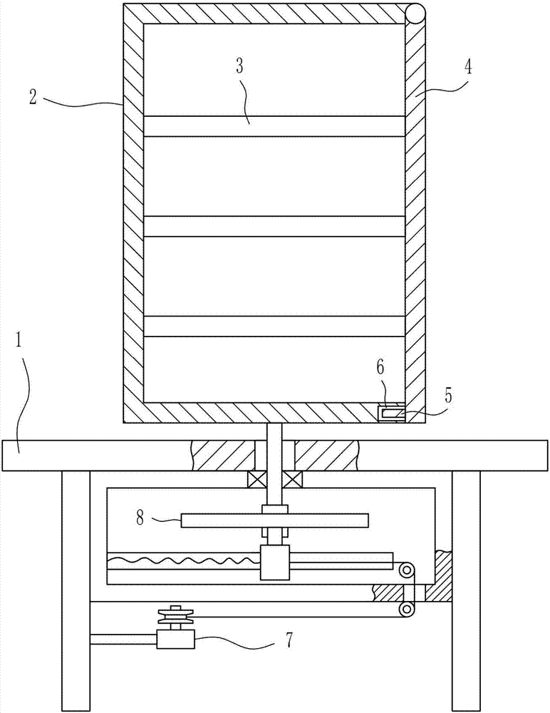
[0034] A kind of ore display equipment, such as Figure 1-5 As shown, it includes a display stand 1, a transparent display box 2, a placement plate 3, a transparent cover plate 4, a block 5, a drive mechanism 7 and a rotation mechanism 8, and a drive mechanism 7 is provided in the middle of the bottom of the display stand 1. On the top of the drive mechanism 7 Connected with a rotating mechanism 8, the rotating mechanism 8 is connected with a transparent display box 2, and the transparent display box 2 is evenly connected with a transparent display box 2, and the upper right side of the transparent display box 2 is rotatably connected with a transparent cover plate 4, and the transparent cover plate 4 A block 5 is connected to the lower left side, and a first groove 6 is formed on the right part of the bottom wall of the transparent display box 2, and the first groove 6 cooperates with the block 5 .
Embodiment 2
[0036] A kind of ore display equipment, such as Figure 1-5 As shown, it includes a display stand 1, a transparent display box 2, a placement plate 3, a transparent cover plate 4, a block 5, a drive mechanism 7 and a rotation mechanism 8, and a drive mechanism 7 is provided in the middle of the bottom of the display stand 1. On the top of the drive mechanism 7 Connected with a rotating mechanism 8, the rotating mechanism 8 is connected with a transparent display box 2, and the transparent display box 2 is evenly connected with a transparent display box 2, and the upper right side of the transparent display box 2 is rotatably connected with a transparent cover plate 4, and the transparent cover plate 4 A block 5 is connected to the lower left side, and a first groove 6 is formed on the right part of the bottom wall of the transparent display box 2, and the first groove 6 cooperates with the block 5 .
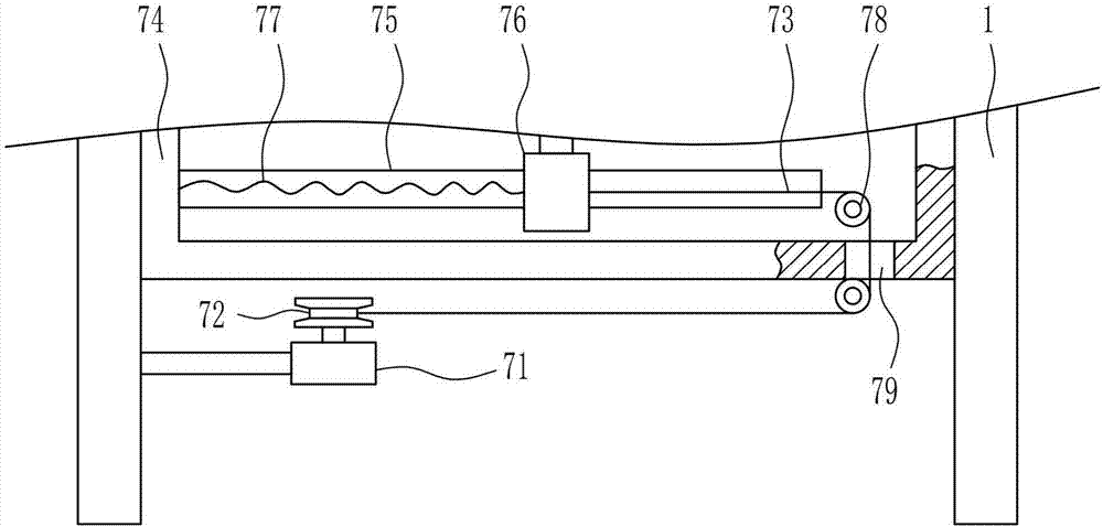
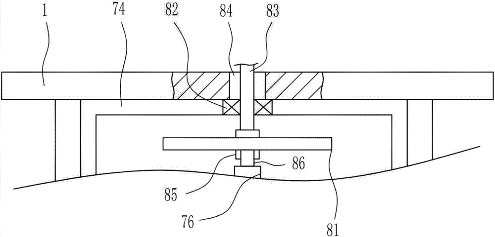
[0037] Drive mechanism 7 comprises motor 71, reel 72, stay cord 73, installa...
Embodiment 3
[0039] A kind of ore display equipment, such as Figure 1-5 As shown, it includes a display stand 1, a transparent display box 2, a placement plate 3, a transparent cover plate 4, a block 5, a drive mechanism 7 and a rotation mechanism 8, and a drive mechanism 7 is provided in the middle of the bottom of the display stand 1. On the top of the drive mechanism 7 Connected with a rotating mechanism 8, the rotating mechanism 8 is connected with a transparent display box 2, and the transparent display box 2 is evenly connected with a transparent display box 2, and the upper right side of the transparent display box 2 is rotatably connected with a transparent cover plate 4, and the transparent cover plate 4 A block 5 is connected to the lower left side, and a first groove 6 is formed on the right part of the bottom wall of the transparent display box 2, and the first groove 6 cooperates with the block 5 .
[0040] Drive mechanism 7 comprises motor 71, reel 72, stay cord 73, installa...
PUM
 Abstract
Description
Claims
Application Information
 - R&D
- Intellectual Property
- Life Sciences
- Materials
- Tech Scout
- Unparalleled Data Quality
- Higher Quality Content
- 60% Fewer Hallucinations
Browse by: Latest US Patents, China's latest patents, Technical Efficacy Thesaurus, Application Domain, Technology Topic, Popular Technical Reports.
© 2025 PatSnap. All rights reserved.Legal|Privacy policy|Modern Slavery Act Transparency Statement|Sitemap|About US| Contact US: help@patsnap.com


