Reinforcing steel bar rust removing device for building

A technology for construction and steel bars, applied in metal processing equipment, grinding/polishing equipment, grinding racks, etc., can solve the problems of complex operation, time-consuming and labor-intensive, and low work efficiency of derusting machines

Inactive Publication Date: 2017-08-25
徐宗林
View PDF4 Cites 16 Cited by
  • Summary
  • Abstract
  • Description
  • Claims
  • Application Information

AI Technical Summary

Problems solved by technology

[0005] In order to overcome the shortcomings of manual derusting of rusted steel bars, time-consuming, laborious, low work efficiency, and easy to be injured in the process of derusting, and the existing derusting machine is complicated to operate, the technical problem to be solved by the present invention It is to provide a kind of time-saving and labor-saving, high work efficiency, not easy to be injured in the process of derusting, and easy to operate.

Method used


Image

  • Reinforcing steel bar rust removing device for building
  • Reinforcing steel bar rust removing device for building
  • Reinforcing steel bar rust removing device for building

Examples


Embodiment 1

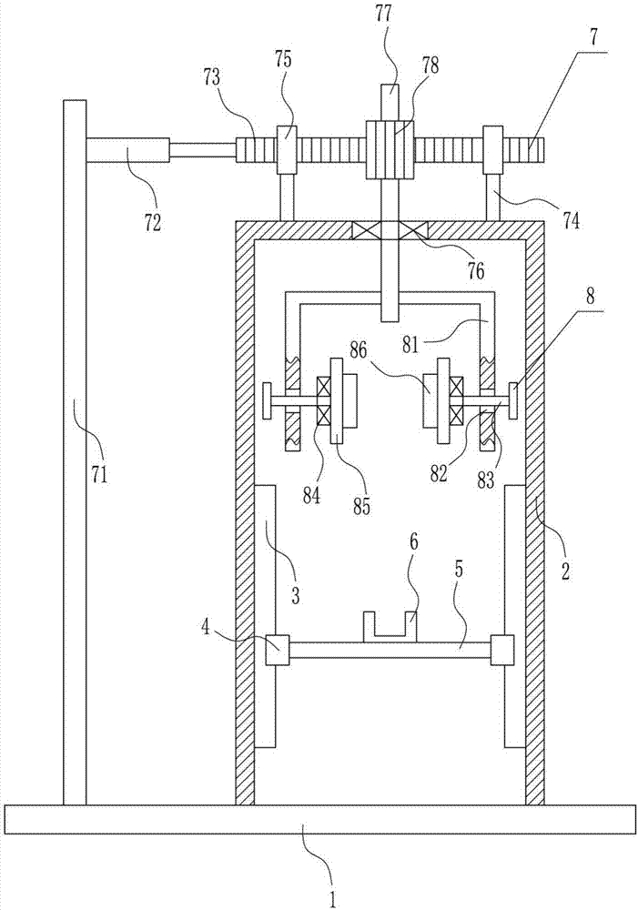
[0027] A kind of derusting equipment for steel bars for construction, such as Figure 1-3As shown, it includes base plate 1, n-frame 2, slide rail 3, first slider 4, horizontal plate 5, ferrule 6, rotation device 7 and adjustment device 8, and the top right side of base plate 1 is installed by bolt connection There is an n-shaped frame 2, the lower part of the left side of the n-shaped frame 2 and the lower part of the right side of the n-shaped frame 2 are installed with a slide rail 3 in a manner connected by bolts, and the slide rail 3 is provided with a first slide block 4 matched with it. The block 4 is slidably matched with the slide rail 3, and a horizontal plate 5 is installed between the first slider 4 on the left side and the first slider 4 on the right side through a bolt connection, and a card is installed in the middle of the top of the horizontal plate 5 through a bolt connection. Sleeve 6, n-type frame 2 is provided with adjusting device 8, and n-type frame 2 to...

Embodiment 2

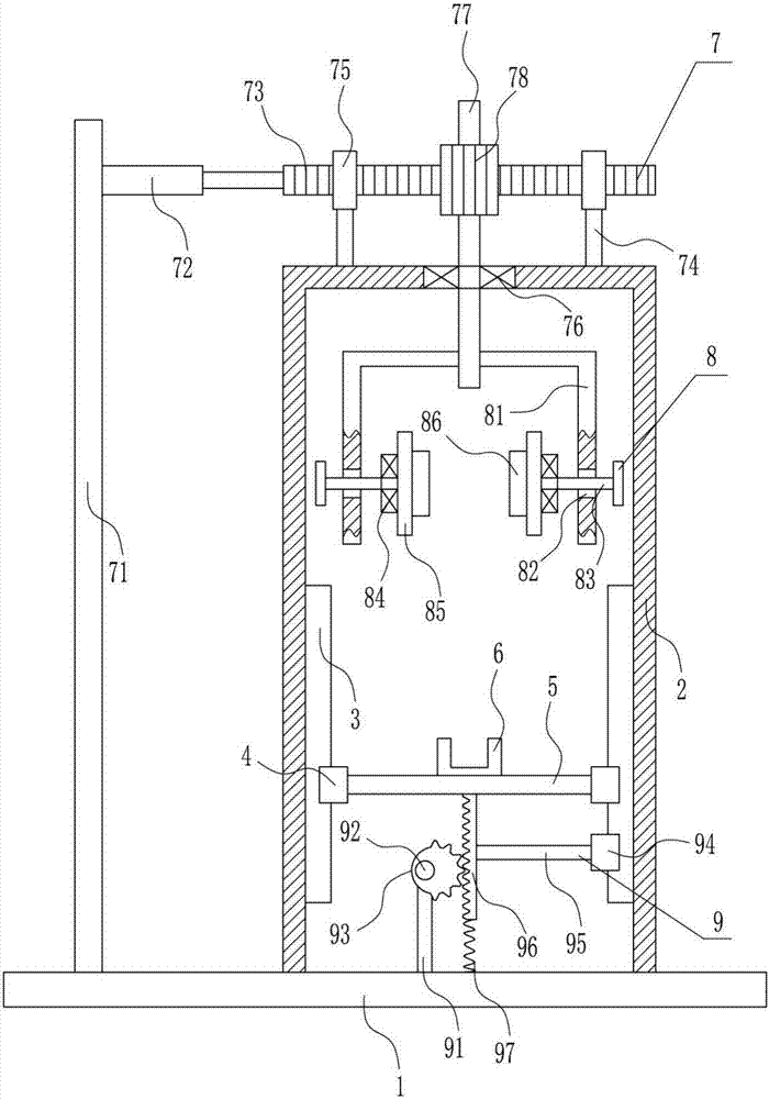
[0029] A kind of derusting equipment for steel bars for construction, such as Figure 1-3 As shown, it includes base plate 1, n-frame 2, slide rail 3, first slider 4, horizontal plate 5, ferrule 6, rotation device 7 and adjustment device 8, and the top right side of base plate 1 is installed by bolt connection There is an n-shaped frame 2, the lower part of the left side of the n-shaped frame 2 and the lower part of the right side of the n-shaped frame 2 are installed with a slide rail 3 in a manner connected by bolts, and the slide rail 3 is provided with a first slide block 4 matched with it. The block 4 is slidably matched with the slide rail 3, and a horizontal plate 5 is installed between the first slider 4 on the left side and the first slider 4 on the right side through a bolt connection, and a card is installed in the middle of the top of the horizontal plate 5 through a bolt connection. Sleeve 6, n-type frame 2 is provided with adjusting device 8, and n-type frame 2 t...

Embodiment 3

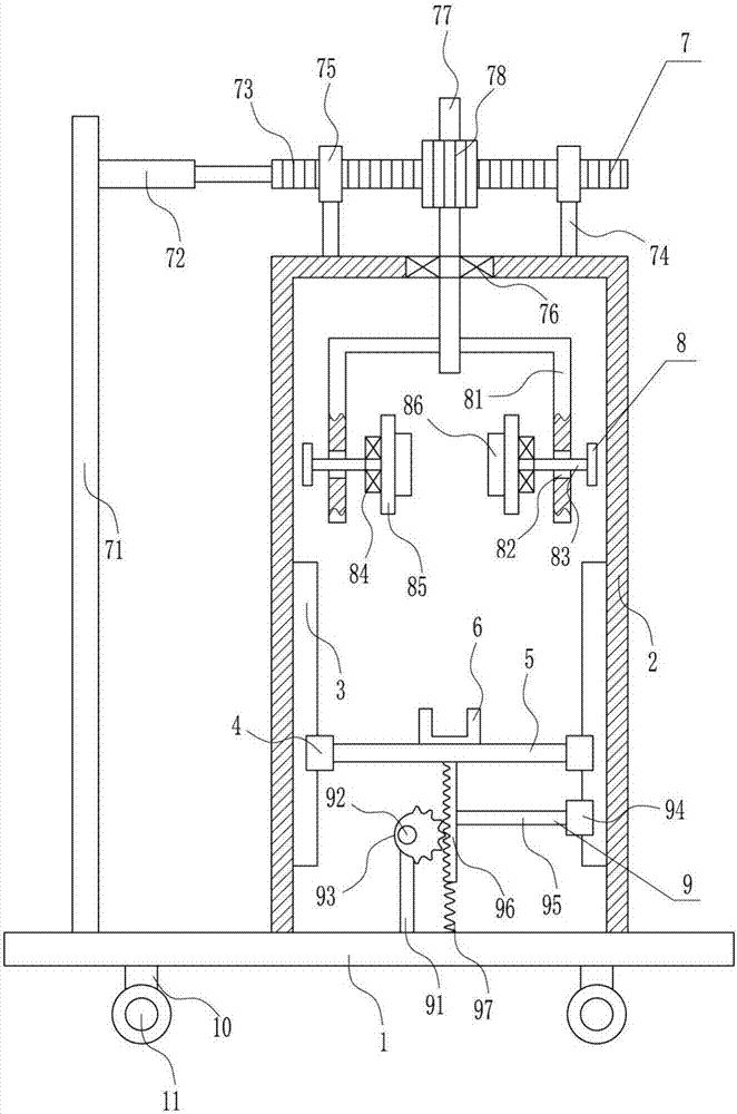
[0032] A kind of derusting equipment for steel bars for construction, such as Figure 1-3 As shown, it includes base plate 1, n-frame 2, slide rail 3, first slider 4, horizontal plate 5, ferrule 6, rotation device 7 and adjustment device 8, and the top right side of base plate 1 is installed by bolt connection There is an n-shaped frame 2, the lower part of the left side of the n-shaped frame 2 and the lower part of the right side of the n-shaped frame 2 are installed with a slide rail 3 in a manner connected by bolts, and the slide rail 3 is provided with a first slide block 4 matched with it. The block 4 is slidably matched with the slide rail 3, and a horizontal plate 5 is installed between the first slider 4 on the left side and the first slider 4 on the right side through a bolt connection, and a card is installed in the middle of the top of the horizontal plate 5 through a bolt connection. Sleeve 6, n-type frame 2 is provided with adjusting device 8, and n-type frame 2 t...


PUM


Abstract

The invention relates to a reinforcing steel bar rust removing device, in particular to a reinforcing steel bar rust removing device for building. The reinforcing steel bar rust removing device for building aims to achieve the technical effects of saving time and effort, being high in work efficiency and easy and convenient to operate and preventing people from being hurt in the dust removal process. The reinforcing steel bar rust removing device for building comprises a base plate, a n-shaped frame, sliding rails, first sliding blocks, a cross plate, a clamping sleeve and the like. The right side of the top of the base plate is provided with the n-shaped frame in a bolted connection manner. The lower portion of the left side face and the lower portion of the right side face in the n-shaped frame are provided with the sliding rails in a bolted connection manner. The first sliding blocks are arranged on the sliding rails and matched with the sliding rails. The first sliding blocks are in sliding fit with the sliding rails. According to the reinforcing steel bar rust removing device, under the action of a cross rod and a second sliding block, a second rack can more stably move up and down, rust removal of a reinforcing steel bar is not influenced, the time and effort are saved, and the work efficiency is high.

Description

technical field [0001] The invention relates to a steel bar rust removal device, in particular to a steel bar rust removal device for construction. Background technique [0002] Steel bar refers to the steel used for reinforced concrete and prestressed reinforced concrete. Its cross section is circular, sometimes square with rounded corners, including smooth round steel bar, ribbed steel bar, and twisted steel bar. Steel bars for reinforced concrete refer to the straight or coiled steel used for reinforced concrete reinforcement. Its shape is divided into two types: smooth round steel bar and deformed steel bar. The delivery state is straight bar and coiled round. [0003] If the steel bar is placed for a long time, the surface of the steel bar will be rusted, and the rusted steel bar will affect the use of the steel bar, which will reduce the load-bearing capacity of the steel bar. Manual derusting of the rusted steel bar is time-consuming, laborious, low-efficiency, and ea...

Claims


Application Information

Patent Timeline
Patent Type & Authority Applications(China)
IPC IPC(8): B24B27/033B24B41/02
CPCB24B27/033B24B27/0092B24B41/02
Inventor 徐宗林
Owner 徐宗林
Why Eureka
Try Eureka