Lifting type drip edge molding system

A drip trough and lift-type technology, which is applied in the field of lift-type drip trough forming systems, can solve the problems of axial offset of the forming strip 4, horizontal offset of the drip trough, inaccurate positioning of the drip trough, etc. The effect of ensuring processing quality and ensuring position accuracy

Active Publication Date: 2017-08-25
JIANGSU SHENGLE MACHINERY
View PDF7 Cites 3 Cited by
  • Summary
  • Abstract
  • Description
  • Claims
  • Application Information

AI Technical Summary

Problems solved by technology

However, there is a problem of inaccurate positioning of the drip tank in this technical solution, which leads to the following two reasons:
[0004] (1) The forming strip 4 is only pushed up and down by the

Method used


Image

  • Lifting type drip edge molding system
  • Lifting type drip edge molding system
  • Lifting type drip edge molding system

Examples


Embodiment Construction

[0027] The following will clearly and completely describe the technical solutions in the embodiments of the present invention with reference to the accompanying drawings in the embodiments of the present invention. Obviously, the described embodiments are only some, not all, embodiments of the present invention.

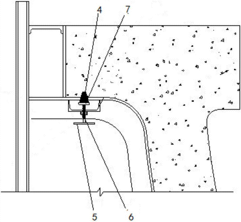
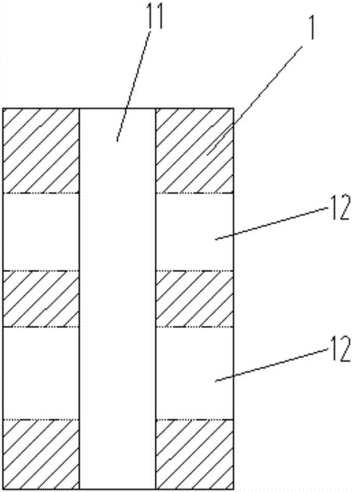
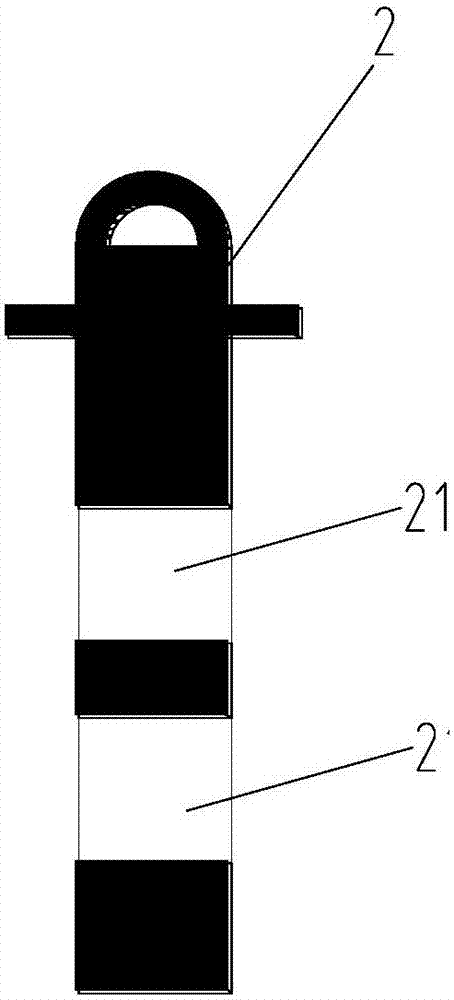
[0028] Such as Figure 1~3 As shown, the lifting drip tank forming system includes a fixed part 1, an inner core 2 and a variable cross-section insert 3; the fixed part 1 is provided with a guide hole 11 for guiding the inner core 2, and the inner core 2 is slidably arranged on the guide In the hole 11, the molding strip 4 is fixedly arranged on the top of the inner core 2; two first through holes 12 are arranged on the fixed part 1; second through holes corresponding to the number of the first through holes 12 are arranged on the inner core 2 21 , the first through hole 12 and the second through hole 21 are used to pass through the insert block 3 with variable cross...


PUM


Abstract

The invention discloses a lifting type drip edge molding system. The lifting type drip edge molding system comprises a fixing part, an inner core and a variable-section insert block, wherein a guide hole for guiding the inner core is formed in the fixing part, and the inner core is glidingly arranged in the guide hole; at least one first penetration through hole is formed in the fixing part; second penetration through holes in equal quantity to the first penetration through holes are formed in the inner core, and the variable-section insert block is arranged in a penetration manner by means of the first penetration through holes and the second penetration through holes. With adoption of the technical scheme, position precision of a molding bar is guaranteed effectively, the height of the inner core relative to the fixing part can be adjusted by controlling the insertion depth of the variable-section insert block, and the height of the molding bar can be adjusted; according to the technical scheme, positioning of the variable-section insert block is reliable, and problems caused by thread failure are solved effectively.

Description

technical field [0001] The invention relates to a forming tooling mechanism used for presetting drip grooves in the manufacture of concrete beams, in particular to a lifting type drip groove forming system. Background technique [0002] In the prior art, most of the precast concrete beam drip grooves are reserved by disassembly, that is, the formwork at the drip groove position is drilled at a certain distance, and the wooden strips or plastic strips formed into the shape of the drip grooves are bolted to the formwork. , After the concrete is poured and formed, remove the fixing bolts before demoulding, lift the beam body out of the formwork, pull out the forming strip from the beam body, and reinstall it on the formwork for reuse. The process of this method is cumbersome, and the formed strips are easily deformed and damaged after repeated use, which not only increases the cost but also easily causes quality defects such as corner drop, cracking or deformation of the be...

Claims


Application Information

Patent Timeline
IPC IPC(8): E04G15/00
CPCE04G15/00
Inventor 汤德良
Owner JIANGSU SHENGLE MACHINERY
Why Eureka
Try Eureka