Small-resistance water segregator capable of controlling flow

A technology for controlling flow and water divider. It is applied in the direction of lift valve, valve details, engine components, etc. It can solve the problems of unstable flow, large branch flow, and small branch flow, and achieve the effect of reducing adverse effects.

Pending Publication Date: 2017-08-25
孙剑军 +2
View PDF5 Cites 2 Cited by
  • Summary
  • Abstract
  • Description
  • Claims
  • Application Information

AI Technical Summary

Problems solved by technology

[0003] In the actual use process, the water diversion branch on the water diversion branch connects the floor heating coil to lay the heating area, and returns to the water diversion branch. This is a floor heating circulation route. The water diversion branch control valve is designed to adjust each The branch flow is stable. For a water distributor with a long number of channels, if the

Method used


Image

  • Small-resistance water segregator capable of controlling flow

Examples


Example Embodiment

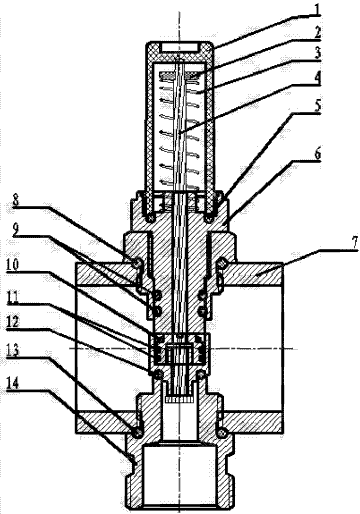
[0015] The present invention will be further described below with reference to the drawings and embodiments.

[0016] The manifold return water flow meter is characterized by: comprising a transparent tube body 1, an indicator mark 2, a spring 3, an indicator rod 4, an o-ring 5, a flow meter body 6, a water manifold body 7, an o-ring 8, and The o-ring 9, the clip 10, the o-ring 11, the o-ring 12, the o-ring 13, and the water outlet 14 form a through cavity inside the flow meter body 6, and the upper port on the inner wall of the through cavity forms a boss, A base is provided at the middle and lower part of the base, a through hole is formed in the middle of the base, a clamp is formed at the bottom end of the outer wall of the base, and a transparent tube body 1 with graduations is detachably installed on the upper end of the flow meter body 6. There is an o-ring 5 between the main body 6 and the transparent tube body 1. The flow meter body 6 has a T-shaped structure. The lower ...


PUM


Abstract

The invention aims at providing a water segregator provided with a flow meter capable of controlling flow, meanwhile reducing influences of impurities or dirt in water and reducing pipeline resistance. A through cavity is formed inside a flow meter main body 6. A boss is formed on an upper port of the inner wall of the through cavity, the lower middle portion of the inner wall of the through cavity is provided with a base, a through hole is formed in the middle of the base, a clamp is formed at the bottom end of the outer wall of the base, a transparent pipe body 1 with scales is detachably installed at the upper end of the flow meter main body 6, an O-shaped ring 5 is arranged between the flow meter main body 6 and the transparent pipe body 1, the flow meter main body 6 is of a T-shaped structure, the lower end of the flow meter main body 6 is provided with an external thread and is in threaded connection with a connection base with an internal thread, an external thread of the connection base is in threaded connection with a distributed water pipe main body, the reducing inner end of the T-shaped structure of the connection base is provided with an O-shaped ring 8, the small-diameter end of the flow meter main body 6 penetrates through the connection base, the lower end is provided with the clamp 10, an indication rod 4 penetrates through the flow meter main body 6, a spring 3 is arranged on the outer side of the upper end of the indication rod 4, and an indication mark 2 is arranged on the upper end side of the spring 3.

Description

Technical field [0001] The invention relates to a water separator for controlling flow. Background technique [0002] The water divider is a water divider device used to connect each heating pipe to supply and return water in the water system. At present, the commonly used water dividers include brackets and water distribution main pipes and water distribution main pipes fixedly installed on the brackets. The water distribution main pipes are fixedly connected with multiple water distribution joints, and the water distribution main pipes are fixedly connected with multiple water distribution joints. , The circulating water in the water diversion main pipe is connected to each of the smaller circulating pipes through the water diversion joint, and finally the circulating water in the circulating pipe returns to the water diversion main pipe through the water diversion joint, and the return water in the water diversion main pipe passes through the geothermal heating The temperatur...

Claims


Application Information

Patent Timeline
IPC IPC(8): F16K37/00F16K27/00F16K1/32
CPCF16K1/32F16K27/00F16K37/00
Inventor 孙剑军孙军华孙敏夏
Owner 孙剑军
Why Eureka
Try Eureka