
Liquid crystal display device

A liquid crystal display device and liquid crystal layer technology, applied in nonlinear optics, instruments, optics, etc., can solve problems such as color cast and black screen shining

Active Publication Date: 2017-08-25
TCL CHINA STAR OPTOELECTRONICS TECH CO LTD
View PDF5 Cites 15 Cited by
  • Summary
  • Abstract
  • Description
  • Claims
  • Application Information

AI Technical Summary

Problems solved by technology

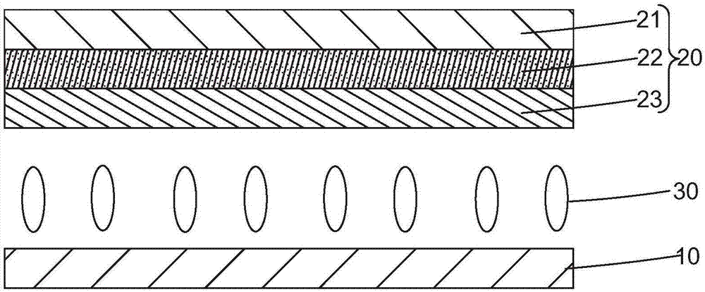
In the optical path of the liquid crystal display panel, the actual optical path of the vertically incident light and the obliquely incident light passing through the liquid crystal layer 30 are different, such as image 3 As shown, when the pixel spacing layer 221 and the red color-resist unit 223 and the green color-resist unit 224 containing the quantum dot material stand on the encapsulation layer 23 at the same height, almost all the light can be incident on the red color-resist unit containing the quantum dot material. The resistance unit 223 and the green color resistance unit 224 have a maximum incident angle a close to 90°, so that under the black picture signal, even if a black picture with a brightness as low as 0.05 nits is displayed at the front view angle, in the direction of squinting, it is likely to be caused by The deviation of the optical path produces a change in polarization, and the quantum dot material is excited due to light leakage at the viewing angle, which in turn causes the black screen to appear bright and color cast when displayed at a large viewing angle

Method used


Image

  • Liquid crystal display device
  • Liquid crystal display device
  • Liquid crystal display device

Examples


Embodiment Construction

[0034] In order to further illustrate the technical means adopted by the present invention and its effects, the following describes in detail in conjunction with preferred embodiments of the present invention and accompanying drawings.

[0035] see Figure 4 , the liquid crystal display device of the present invention includes a liquid crystal panel 800 and a backlight module 900 arranged below the liquid crystal panel 800; a liquid crystal layer 300 between the first substrate 100 and the second substrate 200;

[0036] The first substrate 100 includes a first base substrate 110, and a quantum dot color filter 120 and an encapsulation layer 130 arranged on the side of the first base substrate 110 close to the liquid crystal layer 300 from top to bottom in sequence; wherein, the The encapsulation layer 130 encapsulates and protects the quantum dot color filter 120, and plays a role of planarization.

[0037] Such as Figure 5 As shown, the quantum dot color filter 120 includ...


PUM


Abstract

The invention provides a liquid crystal display device. A liquid crystal panel of the liquid crystal display device comprises a first substrate and a second substrate which are arranged vertically and oppositely, wherein the first substrate comprises a first substrate body, a quantum dot colored filter and a packaging layer from top to bottom sequentially; the quantum dot colored filter comprises pixel spacer layers and multiple color resistor units spaced by the pixel spacer layers; the multiple color resistor units comprise a first color resistor unit, a second color resistor unit and a third color resistor unit, at least one of the color resistor units is a quantum dot color resistor unit, and in the quantum dot colored filter, a transparent stacking layer is further arranged between the quantum dot color resistor unit and the packaging layer, so that the quantum dot color resistor unit stands on the packaging layer from a higher height as compared with the pixel spacer layers; the phenomena that the black screen of the liquid crystal device presents shining and color cast during large-viewing-angle display can be prevented, and the display effect is improved.

Description

technical field [0001] The invention relates to the field of display technology, in particular to a liquid crystal display device. Background technique [0002] With the development of science and technology and the progress of society, people are increasingly dependent on information exchange and delivery. As the main carrier and material basis of information exchange and transmission, display devices have become a hotspot and highland that many scientists engaged in information optoelectronic research are vying to seize. [0003] Quantum Dots (Quantum Dots, referred to as QD) are invisible to the naked eye, extremely small inorganic nanocrystals, most of which are three-dimensional nanomaterials composed of II-VI or III-V elements. Due to the quantum confinement effect, the transport of electrons and holes inside it is restricted, so that the continuous energy band structure becomes a separated energy level structure. Whenever excited by external energy such as light or ...

Claims


Application Information

Patent Timeline
Patent Type & Authority Applications(China)
IPC IPC(8): G02F1/1335G02F1/13357
CPCG02F1/133514G02F1/133606G02F1/133614
Inventor 陈黎暄
Owner TCL CHINA STAR OPTOELECTRONICS TECH CO LTD
Learn More