Aerocraft

An aircraft and frame technology, applied in the aviation field, can solve the problems of multi-rotor aircraft layout confusion, overload of three-axis gyroscope, electromagnetic interference of components, etc., and achieve the effect of simple structure, less hybrid control and high fault tolerance

Inactive Publication Date: 2017-08-29
瑞电恩吉能源技术(深圳)有限公司
View PDF5 Cites 8 Cited by
  • Summary
  • Abstract
  • Description
  • Claims
  • Application Information

AI Technical Summary

Problems solved by technology

However, during the flight, if the attitude is too large, it will easily cause the three-axis gyroscope in the flight control system to be overloaded (overrange).
[0004] In addition, the layout of the existing multi-rotor aircraft is chaotic. Because it contains a variety of sensors, circuit modules, control modules, etc., mutual electromagnetic interference between components is likely to occur, which can easily lead to loss of control and crash of the aircraft.

Method used


Image

  • Aerocraft
  • Aerocraft
  • Aerocraft

Examples


Embodiment 1

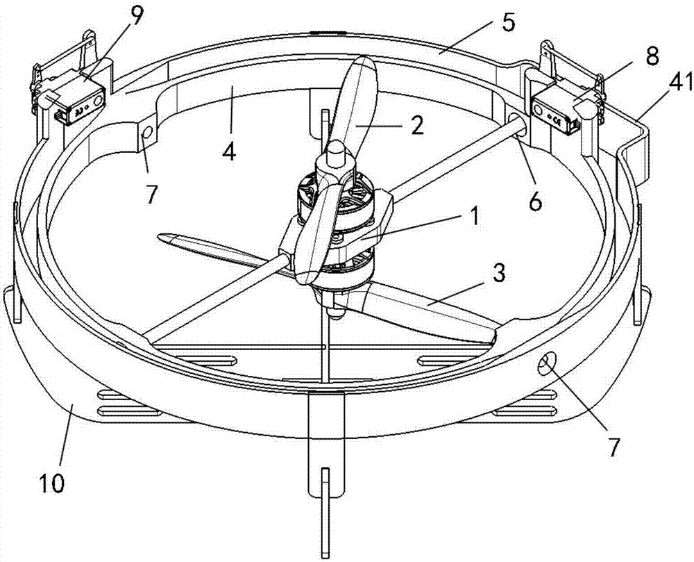
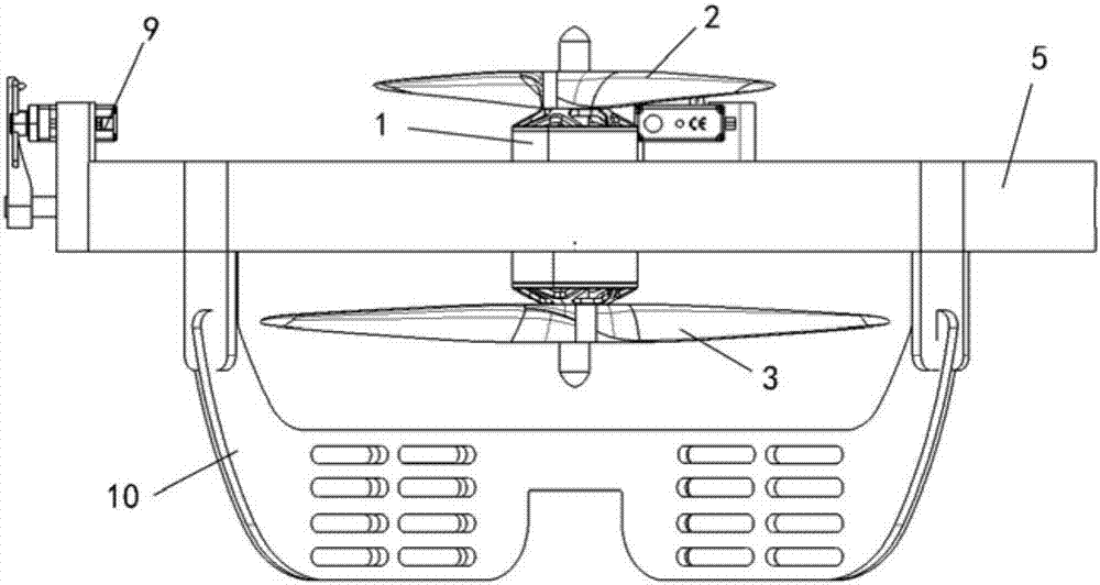
[0038] refer to Figure 1~3 As shown, the present invention provides an aircraft, which mainly includes a main body 1 , a first propeller 2 , a second propeller 3 , a first frame 4 and a second frame 5 .

[0039] Specifically, the first propeller 2 and the second propeller 3 are arranged on the front and back sides of the main body 1 respectively, and their rotation directions are opposite to overcome the torque generated by the rotation. The first frame 4 is arranged around the main body 1 , and is pivotally connected to the main body 1 through a first shaft 6 , so that the main body 1 can turn over in a first direction relative to the first frame 4 . The second frame 5 is arranged around the first frame 4 (the second frame is located on the outer side of the main body relative to the first frame), and the second frame 5 is pivotally connected with the first frame 4 through the second shaft 7, so that the first frame 4 It can be reversed in the second direction relative to t...

Embodiment 2

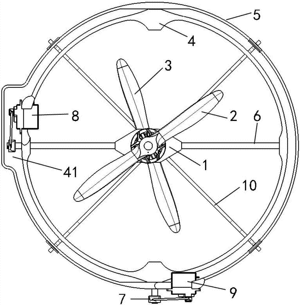
[0046] Such as Figure 4 As shown, another aircraft provided by the present invention mainly includes a first propeller 2 , a second propeller 3 , a first frame 4 , a second frame 5 , a first shaft 6 and a second shaft 7 .

[0047] This embodiment is different from Embodiment 1 in that the aircraft does not include a main body 1, and the first propeller 2 and the second propeller 3 are directly arranged on the first shaft 6, and they are arranged in the same direction.

[0048]Specifically, the first shaft 6 is disposed in the first frame 4 , and its two ends are pivotally connected to the first frame 4 respectively. The first propeller 2 and the second propeller 3 are arranged on the first shaft 6 , therefore, the first propeller 2 and the second propeller 3 can turn over synchronously in the first direction relative to the first frame 5 when the first shaft rotates. The first propeller 2 and the second propeller 3 face the same direction, are located at symmetrical position...

Embodiment 3

[0051] Such as Figure 5 As shown, another aircraft provided by the present invention mainly includes a first propeller 2 , a second propeller 3 , a first frame 4 , a second frame 5 , a first shaft 6 and a second shaft 7 .

[0052] This embodiment is different from Embodiment 1 in that the aircraft does not include a main body 1, and the first propeller 2 and the second propeller 3 are directly arranged on the first shaft 6, and the two are arranged in opposite directions.

[0053] Specifically, the first shaft 6 is disposed in the first frame 4 , and its two ends are pivotally connected to the first frame 4 respectively. The first propeller 2 and the second propeller 3 are arranged on the first shaft 6 , therefore, the first propeller 2 and the second propeller 3 can turn over synchronously in the first direction relative to the first frame 5 when the first shaft rotates. The first propeller 2 and the second propeller 3 face in opposite directions and are located at symmetri...


PUM


Abstract

The application provides an aerocraft which includes a main body; a first propeller and a second propeller, which are arranged respectively on the front and the back sides of the main body and are rotated in opposite directions; a first framework, which surrounds the main body and is pivoted to the main body through a first shaft, so that the main body can turn over in a first direction relative to the first framework; a second framework, which is pivoted to the first framework through a second shaft, so that the first framework can turn over in a second direction relative to the second framework, wherein the first direction is different from the second direction. The aerocraft is provided with double propellers which are arranged on the main body and rotate in opposite directions, so that torque generated by the propellers can be overcome. The aerocraft can fly to any directions since the main body can turn over relative to the first framework and the first framework can turn over relative to the second framework.

Description

technical field [0001] Embodiments of the present invention relate to the field of aviation technology, and in particular to an aircraft. Background technique [0002] With the development of science and technology, multi-rotor aircraft are more and more widely used in various industries, so they are favored by the general public and enterprises. [0003] At present, the rotors of multi-axis aircraft on the market are all multi-axis horizontal installations. In order to realize the translation of the aircraft, only by adjusting the speed difference of multiple rotors, the body can fly at an angle with the bottom surface, so that the horizontal direction can be obtained. The force can realize the attitude of the aircraft such as forward, backward, left, right or rotation around the axis body. However, during the flight, if the attitude is too high, the three-axis gyroscope in the flight control system will be overloaded (overrange). [0004] In addition, the layout of exist...

Claims


Application Information

Patent Timeline
Patent Type & Authority Applications(China)
IPC IPC(8): B64C27/08B64C27/10
CPCB64C27/08B64C27/10
Inventor 白振业曹合冰王瑞祥
Owner 瑞电恩吉能源技术(深圳)有限公司
Why Eureka
Try Eureka