Lifting sun-drying frame with loop-chain supporting arms

A technology of supporting arms and lifting racks, applied in the field of lifting drying racks, can solve the problems of complex structure of lifting racks, affecting the use function, and high folding height, achieving outstanding anti-interference performance, easy cleaning, and overcoming the effects of unbalanced loads.

Pending Publication Date: 2017-08-29
叶柏美
View PDF8 Cites 0 Cited by
  • Summary
  • Abstract
  • Description
  • Claims
  • Application Information

AI Technical Summary

Problems solved by technology

However, the structure of the lifting frame is complex, the folding height is high, and it is not beautiful when it is in the folded state when it is not in use. Moreover, because of its many parts, it is easy to seriously affect the function of use due to the failure of a certain part after long-term outdoor use.

Method used


Image

  • Lifting sun-drying frame with loop-chain supporting arms
  • Lifting sun-drying frame with loop-chain supporting arms
  • Lifting sun-drying frame with loop-chain supporting arms

Examples


Embodiment 1

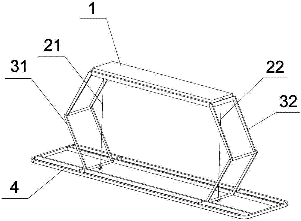
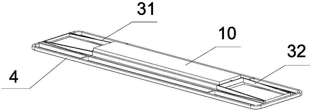
[0032] Embodiment 1, with reference to attached figure 1 , 2 , 3, 4:

[0033] The elevating drying rack with chain support arms provided by the present invention comprises a top mounting frame 1, and the top mounting frame 1 is fixed on the ceiling through a suspension mechanism. The top mounting frame can be a whole mounting frame or shell, or it can be divided into two sections. Because it is fixed on the ceiling, the position cannot change between the two sections. Therefore, these two sections can still be regarded as forming a top mounting bracket and form a link in the chain link structure described below.

[0034] The drying frame also includes a foldable lifting frame, and the lifting frame includes a left chain support arm 31 , a right chain support arm 32 and a bottom frame 4 . The left chain support arm 31 and the right chain support arm 32 are as symmetrical as possible, and the left chain support arm 31 and the right chain support arm 32 both include an upper a...

Embodiment 2

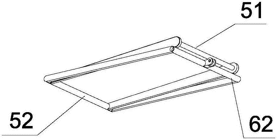
[0044] Embodiment 2, with reference to Figure 5-8 , 9a, 9b, 10:

[0045] In this embodiment, the lower part of the lower arm frame 6 is hinged to the bottom frame 4, and the lower frame bar of the lower arm frame has a sunken part 63, which can accommodate the upper arm frame 5 when folded and reduce the thickness in the folded state. Other parts of this embodiment are the same as Embodiment 1, in Figure 5-8 , 9a, 9b, 10, the reference numerals and Figure 1-4 The same means the same.

Embodiment 3

[0046] Embodiment 3, with reference to Figure 11 , 12a , 12b, 13a, 13b:

[0047] This embodiment mainly introduces the connection structure between the stay rope and the lifting frame. Such as Figure 11 As shown, the middle part of the lower frame bar of the lower arm frame is provided with a connecting mechanism 70 connected with the rotating shaft 7, and the connecting mechanism 70 with the rotating shaft 7 in the left part is connected with the left pull cord 21, and in the right part The connecting mechanism 70 with the rotating shaft 7 is connected with the right stay cord 22 . The force point of the connecting mechanism with a rotating shaft and the pull rope is located on one side of the hinge axis of the lower arm frame and the bottom frame, and is on the opposite side to the bending direction of the side chain support arm, so as to provide side support when the pull rope is pulled up. The partial force makes this side link chain support arm easy to fold.

[004...


PUM


Abstract

The invention provides a lifting sun-drying frame with loop-chain supporting arms. The sun-drying rack comprises a top mounting frame body and is characterized by further comprising a foldable lifting frame body; the lifting frame body comprises a left loop-chain supporting arm, a right loop-chain supporting arm and a bottom frame body; the left loop-chain supporting arm and the right loop-chain supporting arm separately comprise an upper arm frame body and an lower arm frame body; the upper parts of the upper arm frame bodies are hinged to the top mounting frame body, the lower parts of the upper arm frame bodies are hinged to the upper parts of the lower arm frame bodies, the lower parts of the lower arm frame bodies are hinged to the bottom frame body, and a closed chain-shaped structure is formed; and the hinged rotating axis direction is the front-back direction. The lifting sun-drying frame has the outstanding characteristics that the stability is good, the load imbalance on the two sides of a sun-drying mechanism can be overcome, the anti-interference performance is outstanding, the device can stably work without shaking in a strong wind environment, in addition, the number of integral structural parts of the device is greatly lower than that of a traditional shear shank structure, and therefore the cost can be reduced, meanwhile, the safety can be greatly improved and cleaning can be easy.

Description

technical field [0001] The invention relates to a drying device, in particular to an elevating drying rack suspended on the sun room ceiling, balcony ceiling, bay window and other places. Background technique [0002] At present, the common lifting and drying racks suspended on the sun room roof, balcony ceiling, bay window and other places, the drying rod is connected with the steel wire rope on the hinged rope roller to achieve the purpose of lifting, in order to prevent the drying rod from hanging due to the wire rope There is no restraint shaking in the horizontal direction, and parallel connecting rods are installed on both sides to limit the horizontal swing in one direction, but the vertical direction is still not well restrained, especially for drying items other than clothing , For example, when pickling food, new year's goods, agricultural and local specialties and other products, the traditional parallel connecting rod frame is not enough to maintain the front and...

Claims


Application Information

Patent Timeline
IPC IPC(8): F26B9/00F26B9/02
CPCF26B9/00F26B9/02
Inventor 叶柏美
Owner 叶柏美
Why Eureka
Try Eureka