Tunnel surrounding rock deformation distributed optical fiber monitoring method and device based on pipe-shed support

A technology of distributed optical fiber and surrounding rock deformation, which is applied in the direction of measuring devices, optical devices, instruments, etc., can solve the problems of lack of perfect distributed optical fiber and monitoring technology, and achieve simple data collection and extraction, and low monitoring cost. Low, favorable effect on data collection, transmission and construction

Pending Publication Date: 2017-08-29
INST OF ROCK & SOIL MECHANICS CHINESE ACAD OF SCI +1
View PDF7 Cites 12 Cited by
  • Summary
  • Abstract
  • Description
  • Claims
  • Application Information

AI Technical Summary

Problems solved by technology

PPP-BOTDA distributed optical fiber is suitable for the detection and monitoring of the health status of large structures. At present, there is no relatively complete distributed optical fiber monitoring technology in the monitoring of tunnel surrounding rock advance support.

Method used


Image

  • Tunnel surrounding rock deformation distributed optical fiber monitoring method and device based on pipe-shed support
  • Tunnel surrounding rock deformation distributed optical fiber monitoring method and device based on pipe-shed support
  • Tunnel surrounding rock deformation distributed optical fiber monitoring method and device based on pipe-shed support

Examples


Embodiment 1

[0053] according to figure 1 , figure 2 , image 3 , Figure 4 , Figure 5 , Image 6 , Figure 7 It can be seen that a distributed optical fiber monitoring method for tunnel surrounding rock deformation based on pipe shed support specifically includes the following steps:

[0054] Step 1. Use the pipe shed drilling rig 10 to drill holes from the guide pipe 2 and the steel pipe 4 to follow up. Drill the monitoring hole 3 and lay the steel pipe 4 horizontally along the set position outside the tunnel excavation outline; the pipe shed steel pipe 4. It is jacked by machinery, and the 4 sections of the steel pipe are connected with screws;

[0055] Step 2. After the top of the steel pipe 4 in the pipe shed is in place, the first groove 1-4 and the second groove 1-5 at the beginning of the first segment of the fiber optic tube single segment 1 are overlapped in series with the fiber conversion extension connector 1-8 , the third groove 1-6 and the fourth groove 1-7 optical ...

Embodiment 2

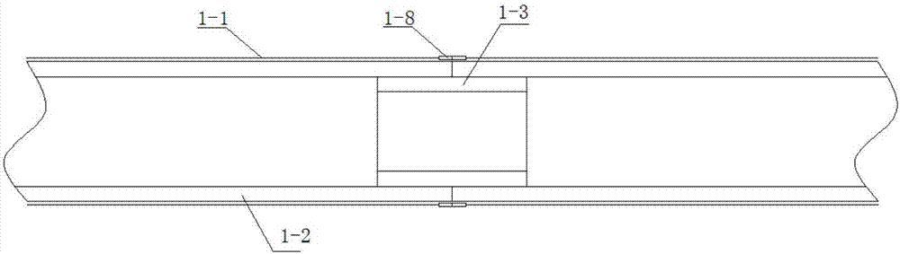
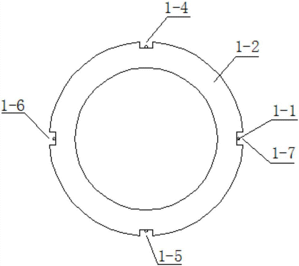
[0063] according to figure 2 , image 3 , Figure 4 , Figure 5 , Image 6 , Figure 7 It can be seen that a distributed optical fiber monitoring device for tunnel surrounding rock deformation based on pipe shed support consists of a single segment of optical fiber measuring pipe 1, optical fiber 1-1, hollow circular pipe 1-2, inner connecting pipe 1-3, the second First groove 1-4, second groove 1-5, third groove 1-6, fourth groove 1-7, extension adapter 1-8, guide pipe 2, monitoring hole 3, pipe shed steel pipe 4 , grout hole 5, guide wall 6, steel arch frame 7, grouting hole 8, optical fiber lead-out pipe 9, and drilling rig 10. The connection relationship is: single segment 1 of optical fiber measuring tube is composed of optical fiber 1-1, extension conversion joint 1-8 and a hollow circular tube 1-2, the outer wall of the single segment 1 of the optical fiber measuring tube is provided with an orthogonally symmetrical first groove 1-4, a second groove 1-5, and a thi...

Embodiment 3

[0070] A method for preparing a single segment of an optical fiber measuring tube, the steps of which are:

[0071] A. According to the length 16m of the supporting steel pipe 4 of the tunnel pipe shed, the single length of the hollow circular pipe 1-2 is determined to be 4m and the quantity is 4 pieces, and the hollow circular pipe 1-2 is grooved, that is, the outer wall of the hollow circular pipe 1-2 The cross-sectional dimensions of the first groove, the second groove, the third groove and the fourth groove opened on the top are all 3mm×3mm, the hollow tube 1-2 the first groove 1-4, the second groove 1-5, the angles between the third groove 1-6 and the fourth groove 1-7 are 180 degrees, 90 degrees (counterclockwise direction) and 90 degrees (clockwise direction);

[0072] B. After the groove is completed, clean the hollow circular tube 1-2 with absolute ethanol to clean the first groove 1-4, the second groove 1-5, the third groove 1-6 and the fourth groove 1-7 The paste s...


PUM


Abstract

The invention discloses a tunnel surrounding rock deformation distributed optical fiber monitoring method and device based on pipe-shed support. The method comprises the following steps: A, drilling a hole in a guide pipe by using a pipe shed drilling machine and enabling a sleeve to follow up; B, sealing an optical fiber joint by using a plastic film after a pipe-shed steel tube are in place; C, gluing an optical fiber measuring tube single section at a steel tube mouth by using an inner connection pipe; D, splicing optical fiber measuring tube single sections; E, installing a drilling hole sealing device; and F, connecting in series the sensing fibers of the optical fiber measuring tube single sections at different monitoring positions of a tunnel pipe-shed support structure by using an extension adapter. The outer sidewall of the optical fiber measuring tube single section has orthogonally symmetrical grooves. The end of the optical fiber measuring tube single section is provided with an extension adapter for easy splicing. The guide pipe is inserted into a steel arch frame in an inclined manner. The pipe-shed steel tube is located inside the guide pipe. The optical fiber measuring tube single sections are located in the pipe-shed steel tube. The method and device achieve tunnel pipe-shed support surrounding rock distributed monitoring and advanced monitoring, and has economical, convenient, anti-interference and durable performance.

Description

technical field [0001] The invention belongs to the technical field of tunnel advance support monitoring, and more specifically relates to a distributed optical fiber monitoring method for tunnel surrounding rock deformation based on pipe shed support, and also relates to a distributed optical fiber for tunnel surrounding rock deformation based on pipe shed support monitoring device. Background technique [0002] In the process of tunnel excavation, it is often encountered in areas such as broken zones, loose zones, weak ground, water gushing, sand gushing, etc. If excavation is carried out under such geological conditions, if no advance pre-support is carried out, collapses are likely to occur. Leading to safety accidents will not only cause economic losses to related enterprises, increase project costs, but also greatly affect project construction progress and construction quality. Before the excavation of existing lines or buildings and rivers and lakes under the tunnel ...

Claims


Application Information

Patent Timeline
Patent Type & Authority Applications(China)
IPC IPC(8): G01B11/16
CPCG01B11/18
Inventor 汤华武松罗红星但路昭吴振君钟明文袁从华戴永浩徐伟然王东英
Owner INST OF ROCK & SOIL MECHANICS CHINESE ACAD OF SCI
Why Eureka
Try Eureka