
A crack monitoring sensor based on otdr technology and its application method
A monitoring sensor and technology technology, applied in instruments, measuring devices, optical devices, etc., can solve problems such as insufficient operability, poor anti-interference ability, and complicated operation, and achieve simple structure, high safety, and high sensitivity. Effect
- Summary
- Abstract
- Description
- Claims
- Application Information
AI Technical Summary
Problems solved by technology
Method used
Image

Examples
Embodiment
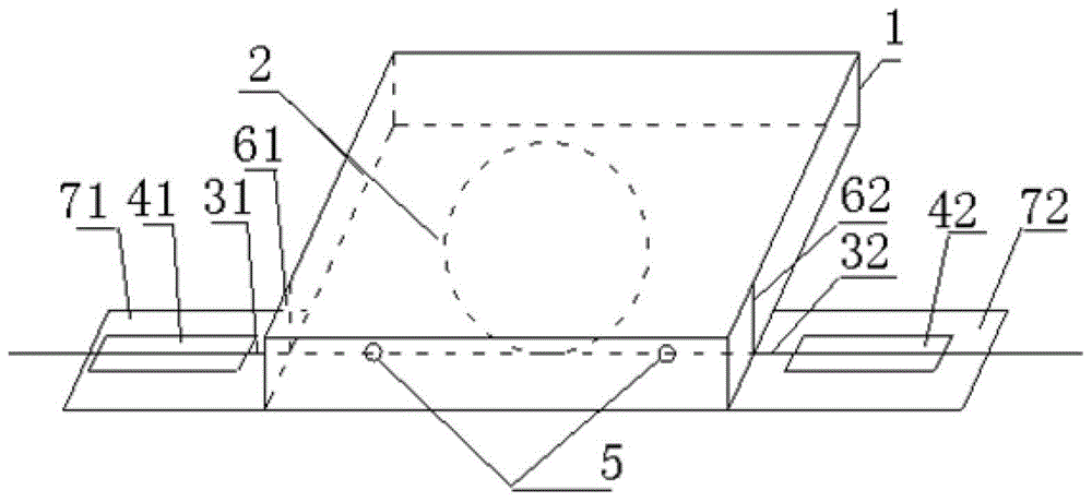
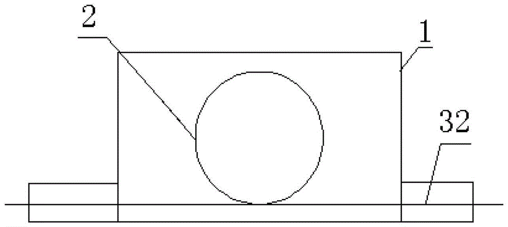
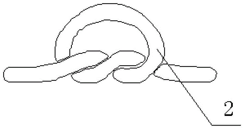
[0016] A crack monitoring sensor based on OTDR technology, such as figure 1 , 2 As shown, it includes a protective box, a bare fiber coil with two ends, and the first and second protected optical fibers. The bare fiber coil is arranged in the protective box, and the bare fiber coil is glued by epoxy resin Pasted in the protective box, the bottom two ends of the protective box are respectively provided with first and second outlets, the first and second outlets are used to lead out the first and second optical fibers with protective layers, and the second 1. The bottom of the protective box below the second outlet is respectively provided with the first and second optical fiber bonding platforms; since the bare optical fiber is easy to break, the bare optical fiber and the optical fiber with the protective layer are welded inside the protective box, and then the optical fiber with the protective layer is fused Lead out, not easy to break, that is, one end of the first protecti...
PUM
| Property | Measurement | Unit |
|---|---|---|
| diameter | aaaaa | aaaaa |
| diameter | aaaaa | aaaaa |
Abstract
Description
Claims
Application Information