
Battery end testing device

A testing device and battery technology, which is applied to measuring devices, measuring device casings, components of electrical measuring instruments, etc., can solve the problems of easily damaged battery shrapnel, damage to shrapnel, affecting efficiency, etc., and achieve the effect of good conduction effect.

Active Publication Date: 2017-08-29
GOERTEK INC
View PDF5 Cites 2 Cited by
  • Summary
  • Abstract
  • Description
  • Claims
  • Application Information

AI Technical Summary

Problems solved by technology

For example, the method of manual plugging and unplugging increases a large number of manual operations, which consumes man-hours and affects efficiency
Moreover, it is easy to damage the battery shrapnel or lift the battery shrapnel or the product during the unplugging process, causing damage to the electronic product
For example, the way that the cylinder drives the conductive block to press down is prone to problems such as poor contact, damage to the shrapnel, and lifting the product due to factors such as deformation of the battery shrapnel, small longitudinal contact surface of the battery shrapnel, and assembly errors when pressing down.

Method used


Image

  • Battery end testing device
  • Battery end testing device
  • Battery end testing device

Examples


Embodiment Construction

[0029] Various exemplary embodiments of the present invention will now be described in detail with reference to the accompanying drawings. It should be noted that the relative arrangements of components and steps, numerical expressions and numerical values ​​set forth in these embodiments do not limit the scope of the present invention unless specifically stated otherwise.

[0030] The following description of at least one exemplary embodiment is merely illustrative in nature and in no way taken as limiting the invention, its application or uses.

[0031] Techniques, methods and devices known to those of ordinary skill in the relevant art may not be discussed in detail, but where appropriate, such techniques, methods and devices should be considered part of the description.

[0032] In all examples shown and discussed herein, any specific values ​​should be construed as exemplary only, and not as limitations. Therefore, other instances of the exemplary embodiment may have dif...


PUM


Abstract

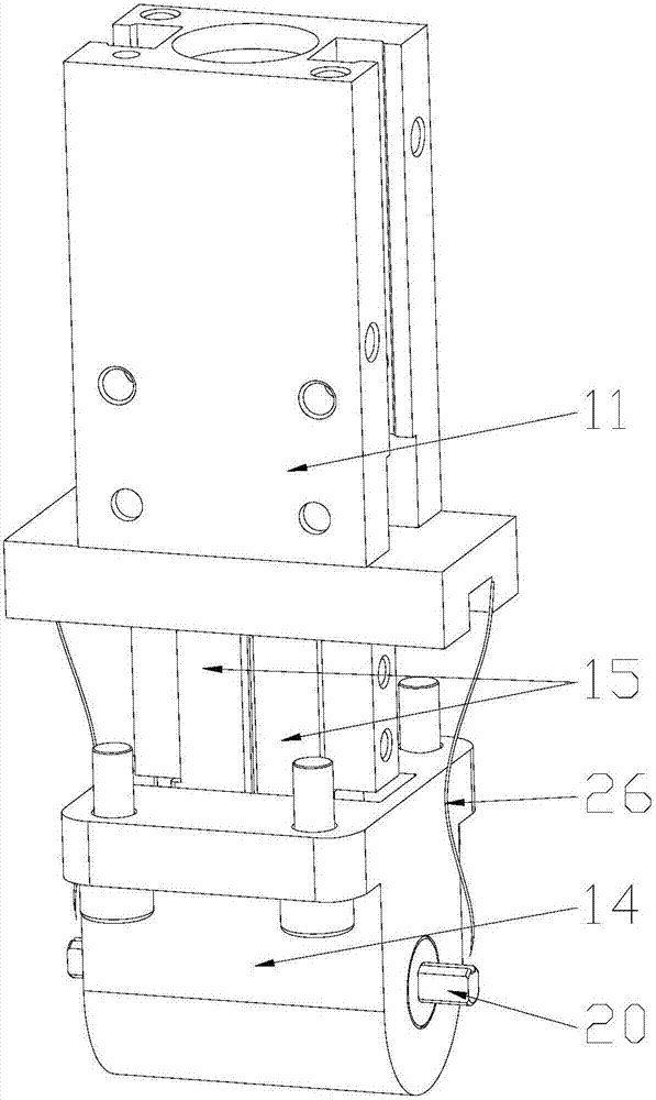
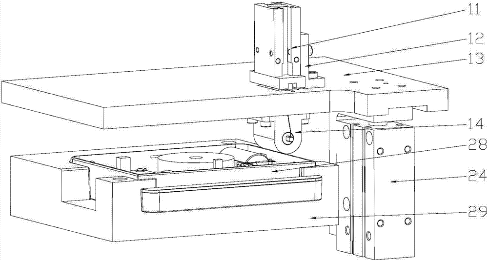
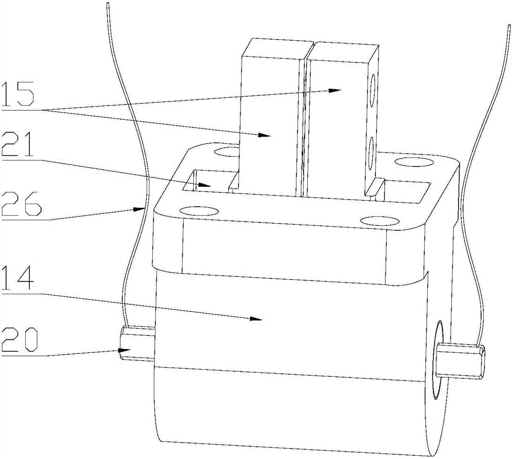
The invention discloses a battery end testing device. The testing device comprises a device body, a driving part and a telescopic part. The device body comprises a sliding cavity extending inwards from the surface. The telescopic part is arranged in the sliding cavity. The telescopic part comprises a sleeving cylinder, an elastic component and a compression component. The elastic component is arranged in the sleeving cylinder. The compression component is connected with the sleeving cylinder in a sliding manner along the axial line direction of the sliding cavity. One end of the compression component abuts against the elastic component and the other end extends out of the sleeving cylinder. The outer end part of the compression component is connected with the contact of a conductive wire. The elastic component is insulated from the contact. The driving component is structured to drive the telescopic part to slide outwards along the axial line direction of the sliding cavity so as to enable the contact to be in elastic contact with the battery end of the to-be-tested component.

Description

technical field [0001] The present invention relates to the technical field of testing devices, and more specifically, relates to a battery terminal testing device for testing the power-on performance of a battery terminal and the operation of each part of an electronic product after power-on. Background technique [0002] At present, household electronic products are developing rapidly. When testing this electronic product, it is necessary to test the power-on performance of the battery terminal and the functional operation of each part of the product after power-on. At present, there are two main ways to realize battery terminal communication: 1. Manually plugging and inserting the conductive block; 2. The cylinder drives the conductive block to realize automatic contact. There are many problems in these two ways in actual use. For example, the way of manual plugging and unplugging increases a lot of manual operations, which consumes man-hours and affects efficiency. Mo...

Claims


Application Information

Patent Timeline
IPC IPC(8): G01R1/04G01R31/36
CPCG01R1/0416G01R31/385
Inventor 景凯凯陈军丁永胜
Owner GOERTEK INC
Learn More