Rotary control system for a device

A technology for control systems and equipment, applied in the direction of control/regulation systems, control components, mechanical control devices, etc., can solve the problems of increasing the volume and complexity of the system, complicated and expensive manufacturing and packaging, etc.

Active Publication Date: 2017-08-29
SCHNEIDER ELECTRIC IND SAS
View PDF6 Cites 3 Cited by
  • Summary
  • Abstract
  • Description
  • Claims
  • Application Information

AI Technical Summary

Problems solved by technology

This has the disadvantage of increasing the size and complexity of the system
Furthermore, such locks can usually only be used by a small number of keys specifically ass

Method used


Image

  • Rotary control system for a device
  • Rotary control system for a device
  • Rotary control system for a device

Examples


Example Embodiment

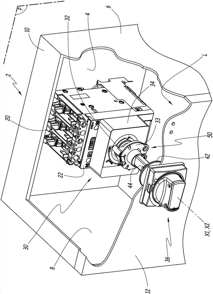
[0039] figure 1 Indicates electrical enclosure 2. The housing 2 includes a rear wall 4 extending substantially in a geometric plane P. The housing 2 also includes top and bottom side walls 6, 8 and 10. The walls 6, 8 and 10 extend at right angles to the geometric plane P. The walls 4, 6, 8 and 10 define the housing L.

[0040] The housing 2 also includes a door 12 that can move reversibly between an open position and a closed position. In the open position, the housing L opens to the outside of the housing 2 and in the closed position, the door 12 closes the housing L. For example, the door 12 is installed to pivot along an axis extending parallel to the plane P such that in its closed position, the door 12 faces the rear wall 4. For example, the door 12 is installed to be fixed to the outer edge of one or the other of the side walls 6 or 8 by a hinge. Here, the housing 12 has a trapezoidal shape with a parallelepiped base. The walls 4, 6, 8 and 10 and the door 12 are made o...


PUM


Abstract

This rotary control system for a device includes a rotary control member, and a rotary control handle, a blocking device that can be selectively moved, when the rotary member is in its first position, between a blocking configuration and a release configuration. This system further includes a locking plate, rotationally mobile about the first axis relative to the rotary member, when the rotary member is in its first position, between a locking position and an unlocked position. The locking plate is such configured that when the blocking device moves between the corresponding locking position and the unlocked position, the blocking device is switched between the blocking configuration and the release configuration.

Description

technical field [0001] The invention relates to a rotation control system for equipment. The invention also relates to an electrical enclosure comprising a controllable electrical device and a rotation control system for controlling the electrical device. Background technique [0002] The invention applies more particularly to rotation control systems for electrical equipment such as circuit breakers. Such systems are known to include a rotary control member that is rotationally displaceable between predetermined positions associated with different electrical states of the electrical device, such as open and closed states. For a circuit breaker, for example, these electrical states correspond to a closed state and an open state. Typically, electrical equipment is placed within the electrical enclosure on the rear wall of the electrical enclosure. A rotary control handle is placed on the door of the enclosure, facing the rear wall, so as to be accessible and actuated by th...

Claims


Application Information

Patent Timeline
IPC IPC(8): H01H9/28G05G5/28
CPCG05G1/08G05G5/28H01H9/282H01H3/20H01H3/08H01H9/281H01H71/56H01H2071/565G05G1/10G05G2505/00H01H19/14H01H19/36H01H2235/01H05K5/0017H05K5/02
Inventor D.辛托姆兹F.皮蒂斯
Owner SCHNEIDER ELECTRIC IND SAS
Why Eureka
Try Eureka