Burst ligation device

A clip and carrier technology, applied in the field of medical devices, can solve the problems of clip stability, inconsistent reliability, delayed operation time, clip performance damage, etc., and achieve the effects of stable and reliable release process, reduced labor intensity, and short structure

Active Publication Date: 2020-03-24
HANGZHOU AGS MEDTECH CO LTD
View PDF4 Cites 0 Cited by
  • Summary
  • Abstract
  • Description
  • Claims
  • Application Information

AI Technical Summary

Problems solved by technology

[0004] The shortcoming of this hair clip device is that when applying force to the frontmost clip, the force needs to be transmitted through the subsequent clips, so the strength of the subsequent clips must be gradually increased, if the frontmost clip is not successful If it is released, the clip at the rear end will fail due to excessive tension, and a new instrument needs to be replaced at this time, which will lead to delays in operation time
Secondly, when the front-end clip is released, the rear-end clips all bear a certain force, so the performance of the clips will be damaged, which will lead to inconsistent stability and reliability of each clip

Method used


Image

  • Burst ligation device
  • Burst ligation device
  • Burst ligation device

Examples


no. 1 approach

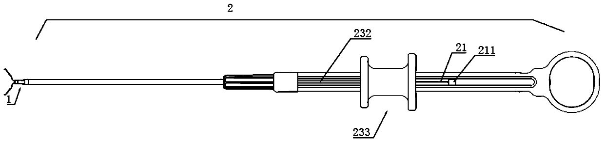
[0081] Such as figure 1 with Figure 16 As shown, the control handle of the present invention includes a handle body 231, a guide tube 232 penetrating through the handle body 231, and a sliding handle 233 connected to the rear end of the guide tube 232. The rear end of the tube 22 is adjacent to the front end of the guide tube 232 , and the rear end of the pulling wire 21 passes through the guide tube 232 . When the slide handle 233 is pushed toward the front end, the guide pipe 232 can push the push pipe 22 to move toward the front end.

[0082] The rear end of the pull wire 21 is provided with a sliding seat 211 that slides along the handle body 231 , and the handle body 231 is provided with a front-end limiting portion, and the sliding seat 211 can slide farthest to the front-end limiting portion. Adopting this kind of conveying part structure, when in use, insert the continuous hair clip device into the endoscope clamp channel, and pass through the front end of the scree...

Embodiment approach

[0084] Such as Figure 17 As shown, as the second embodiment of the delivery control part, the control handle of the present invention includes a handle body 231, a guide tube 232 passing through the handle body 231, and a sliding handle 233 connected to the rear end of the guide tube 232. The sliding handle 233 can be moved forward and backward. Slidingly sleeved on the handle body 231 , the front end of the guide tube is connected to the push tube, the rear end of the pull wire 21 runs through the inside of the guide tube 232 , and the rear end of the pull wire 21 is connected to the sliding handle 233 . The sliding handle 233 can drive the pulling wire 21 to move back and forth.

[0085] Adopt this kind of conveying control structure, at the beginning, insert the continuous hair clip device through the crossing of the endoscope forceps and reach the lesion position, push the sliding handle 233 to the front end and drive the traction wire 21 to move to the front end, and the...

no. 3 approach

[0087] Such as Figure 18 As shown, the third embodiment of the transport control unit has some changes on the basis of the second embodiment. The handle body 231 can be provided with several limit protrusions 2314. When the sliding handle 233 reaches the limit protrusions 2314, it will be stuck or hindered for a while, but when the doctor pushes and pulls the sliding handle with greater force, it can still pass through Limit protrusion and continue to move. The distance between the stopper projections is just the distance to push out one clip or slightly about one clip, so that the doctor can play a prompting role when pushing out the clip like this to prevent excessive force from continuously pushing out several clips all in a row.

[0088] or, as in Figure 19 As shown, it is also possible to add several movably connected limit cards 2315 on the handle body 231, which have a certain friction force with the handle body 231, which can hinder the movement of the sliding hand...


PUM


Abstract

The invention provides a serial ligation device, which includes a clamping part and a delivery control part. The clamping part includes a clip set and a storage tube for storing the clip set. The clip set includes at least two clips arranged axially along the storage tube. Each clip includes a pair of clips, the tail of the clips is provided with a bearing sheet that will deform or break under a predetermined pressure, and the clips form a hole through the carrier sheet; the delivery control part includes a traction line; wherein the traction line passes through the The holes formed by the carrier sheet and the leading ends of the pull wires are blocked by the carrier sheet. Adopting the continuous hair ligation device of the present invention can ensure that the release process of each clip is stable and reliable, and there is no risk of unsuccessful clip release due to the performance degradation of the material connecting the release structure; and the doctor inserts the continuous hair ligation at one time The device can release multiple hemostatic clips to clamp the lesion, which can greatly reduce the operation time.

Description

technical field [0001] The invention belongs to the field of medical devices, in particular to a serial ligation device for treating active bleeding, wound and perforation closure. Background technique [0002] Endoscopy has been born for more than 50 years, and has gone through the stage from disease diagnosis to disease treatment. It has been very effective and reliable in the treatment of some diseases. The stomach and intestines of organisms often suffer from bleeding, mucosal injury or even perforation due to various diseases or accidental injury or injury during endoscopic diagnosis and treatment. For active bleeding, drugs are generally sprayed, high-frequency electricity, laser, argon gas burn the bleeding point, and clip mechanical compression is used for hemostasis. Among them, clip mechanical compression hemostasis is more reliable for the treatment of active bleeding not caused by varicose veins, and has also been recognized by doctors and patients, and is now u...

Claims


Application Information

Patent Timeline
Patent Type & Authority Patents(China)
IPC IPC(8): A61B17/12A61B17/122A61B17/00
CPCA61B17/00234A61B17/12A61B17/1222A61B2017/00017A61B2017/00238A61B17/122A61B17/128A61B17/1227A61B17/1285
Inventor 时百明
Owner HANGZHOU AGS MEDTECH CO LTD
Why Eureka
Try Eureka