Pad

A back and back side technology, applied in the field of pressure pads, can solve the problem that the strength of the raised part on the front side cannot be fully controlled.

Active Publication Date: 2017-08-29
BAUERFEIND GMBH & CO
View PDF17 Cites 4 Cited by
  • Summary
  • Abstract
  • Description
  • Claims
  • Application Information

AI Technical Summary

Problems solved by technology

Likewise, in pressure pads according to the prior art, the strength of action of the protrusions on the front side, in particular the nodules, cannot be adequately controlled.

Method used


Image

  • Pad
  • Pad
  • Pad

Examples


Embodiment Construction

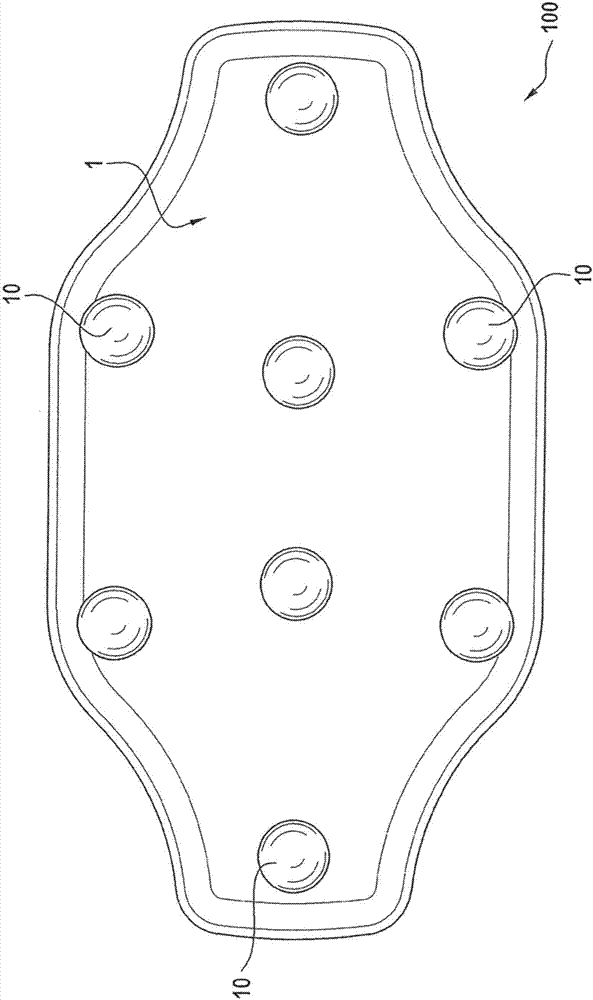
[0051] figure 1 The front side surface 1 of a pressure pad 100 according to the invention is shown. The pressure pad 100 is here a back pressure pad. The pressure pad 100 is integrally made of a soft and elastic material. Surface 1 is rounded at the edges. Hemispherical friction nodules 10 are arranged on the surface 1 . The number and positioning of the friction nodules advantageously lead to stimulation of trigger points by friction massage in the back area.

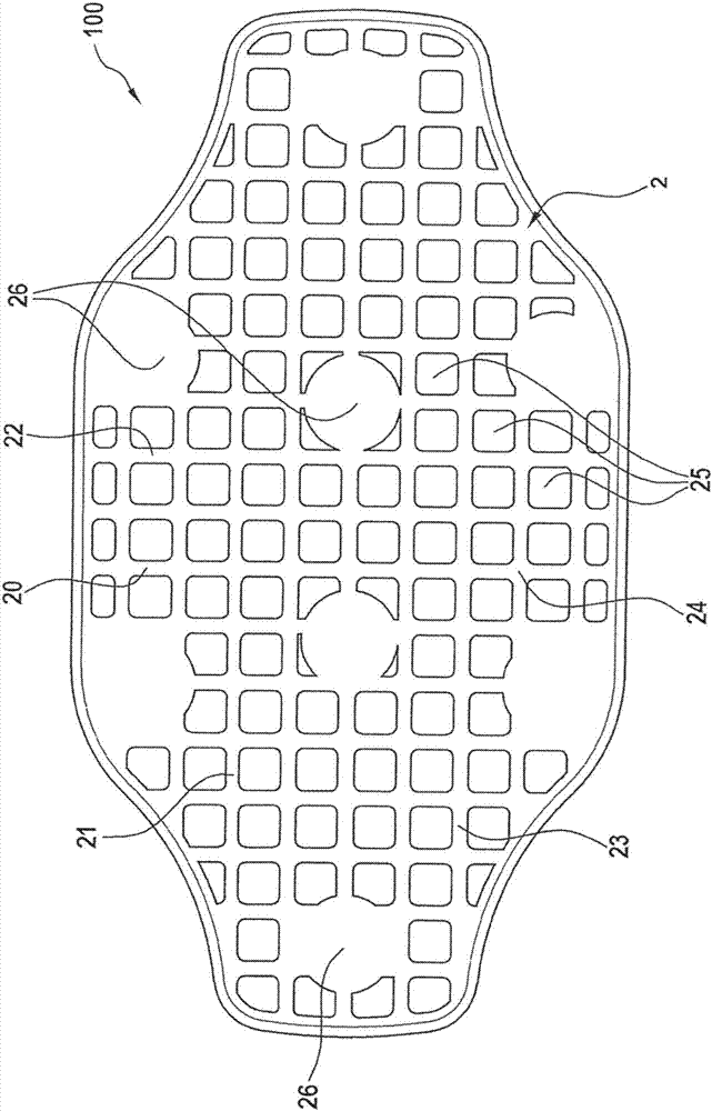
[0052] figure 2 The dorsal surface 2 of the dorsal pressure pad 100 is shown. The surface 2 is formed by the outer surface of a plurality of connections 20 , 21 , 22 , 23 which, via intersections 24 , form a grid structure with interspaces 25 . The intermediate space 25 is thus a depression in the rear surface 2 . For stabilization purposes, the connections 20 , 21 , 22 , 23 are slightly reinforced in the region of the intersection point 24 . In the region of the rear surface 2 opposite the front surface 1 of ...


PUM


Abstract

The invention relates to a pad (100, 300) for a bandage (101) or orthosis; said pad (100) has a front surface (1) and a rear surface (2); at least a subarea of the rear surface (2) has connection pieces (20, 21, 22, 23, 30, 31, 32, 33) which form a mesh structure with interstices (25, 35).

Description

technical field [0001] The invention relates to a pressure pad for bandages and orthoses. The present invention provides an improved pressure pad having a backside with a grid structure. Background technique [0002] Pressure pads are medical pressure pads used to apply and transmit pressure. They are mostly used together with bandages or orthotics, for example in the back, hip, shoulder, arm or leg area. [0003] Various pressure pads are known, for example, from the patent documents EP1688107A1, DE10103545A1, DE2722563A1 and DE102011010827A1. [0004] The three-dimensional shape of such pressure pads on the front side, that is to say the side facing the body of the person wearing the pressure pad and usually pressing against the skin of the person, is quite different, for example in the form of nubs, bumps or air channels. In contrast, the back side of a pressure pad is usually smooth. Fastening elements in the form of buttons, adhesive strips or hook and loop fastener...

Claims


Application Information

Patent Timeline
Patent Type & Authority Applications(China)
IPC IPC(8): A61F5/30
CPCA61F5/028A61F5/30
Inventor 汉斯·B·鲍尔法因德赖纳·朔伊尔曼
Owner BAUERFEIND GMBH & CO
Why Eureka
Try Eureka