
crushing device

A technology of crushing device and containing device, which is applied in the direction of grain processing, etc.

Active Publication Date: 2019-03-15
F L SMIDTH & CO AS
View PDF8 Cites 0 Cited by
  • Summary
  • Abstract
  • Description
  • Claims
  • Application Information

AI Technical Summary

Problems solved by technology

Such a crushing device has many parts and is therefore cost-intensive and maintenance-intensive

Method used


Image

  • crushing device
  • crushing device
  • crushing device

Examples


Embodiment Construction

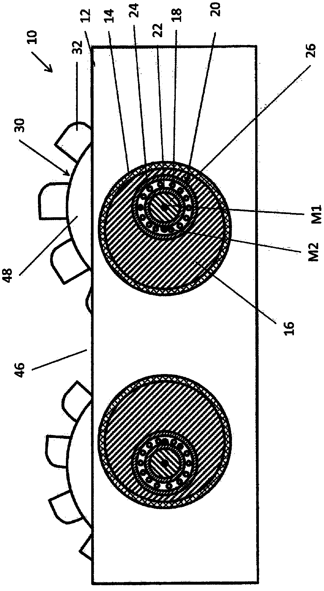
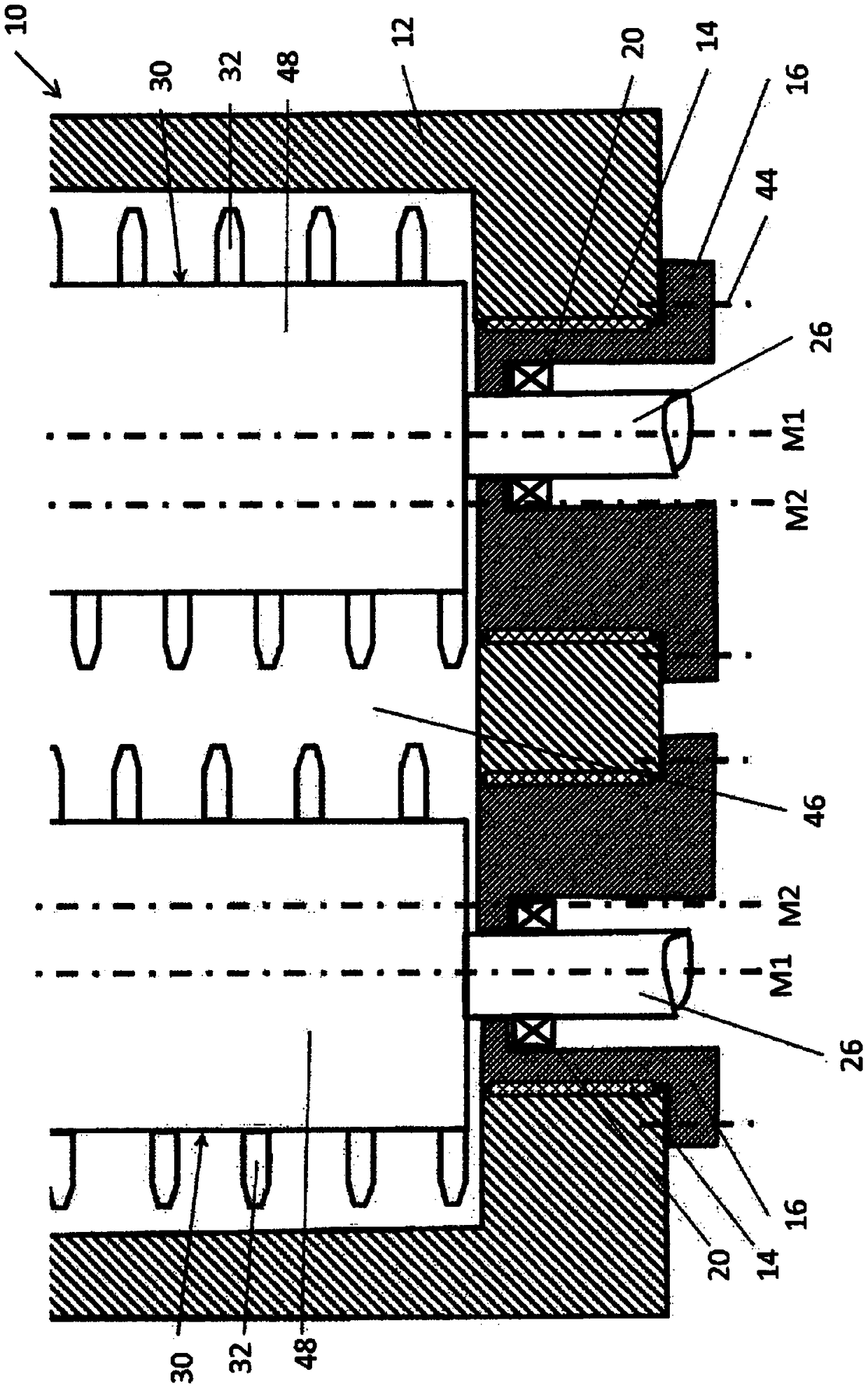
[0032] figure 1 A schematic sectional view of a crushing device, in particular a roller crusher 10 with two crushing rollers 30 is shown. The crushing rollers 30 are arranged parallel to one another and form a crushing gap 46 between one another. The crushing rollers 30 each comprise a shaft portion 26 which extends axially via a roller body 48 fixedly connected to the shaft portion. The roller body 48 has a circular cross section, wherein a plurality of circumferentially spaced apart crushing teeth 32 are arranged on the surface of the roller body 48 .

[0033] The roll crusher 10 has the figure 1 The housing 12 , shown in a rectangular shape, has two circular recesses arranged at the same height, in which a sleeve-shaped receptacle 16 is arranged in each case. The housing is shown in one piece by way of example. It is also conceivable that the housing consists of several housing sections, in particular two housing sections, which will be figure 1 The housing shown in is...


PUM


Abstract

The invention relates to a crushing device (10) for crushing material to be crushed, comprising a housing (12), at least one crushing roller (30), at least one bearing (20) for bearing the crushing roller (30), and at least one substantially sleeve-shaped receiving device (16) arranged between the housing (12) and the bearing (20) in such a way that the receiving device (16) can rotate about its central axis (M2) relative to the housing (12), wherein the bearing (20) is eccentrically mounted in the receiving device (16), such that, via a rotation of the receiving device (16), the bearing (20) moves relative to the housing (12), wherein the crushing device (10) has a pre-tensioning element (38) that is arranged in such a way that it applies the receiving device (16; 36; 56) against the housing (12; 52) with a pre-tensioning force.

Description

technical field [0001] The invention relates to a crushing device for crushing materials to be crushed. Background technique [0002] Known crushing devices, such as roller crushers, have a plurality of crushing rollers arranged parallel to one another, which form a crushing gap between two adjacent crushing rollers. Adjacent crushing rollers are usually driven in opposite directions, so that the material to be crushed moves into the crushing gap. In order to change the crushing degree of the material, it is necessary to make the crushing gap correspondingly larger or smaller. For compact roller crushers, such as screening machines, it has hitherto not been possible to change the crushing gap geometry without retrofitting the existing crushing plant, in particular the crushing tools and the crushing rollers. For larger roller crushers, such as known in document EP2653233B1, it is known to change the gap geometry by adjusting the crushing rollers hydraulically. Such crushi...

Claims


Application Information

Patent Timeline
Patent Type & Authority Patents(China)
IPC IPC(8): B02C4/02B02C4/08B02C4/32
CPCB02C4/32B02C4/02B02C4/08
Inventor 彼得·沙茨托马斯·格恩哈特
Owner F L SMIDTH & CO AS
Learn More