
Light guiding device and board clamping device

A technology of a light guide device and a board card, which is applied to lighting devices, components of lighting devices, optics, etc., can solve problems such as increased labor costs, unevenness of LED lights 12′, and influence on the effect of prompting signals, and achieves simple structure, Enhance the effect of function status prompts and reduce the effect of light decay

Active Publication Date: 2017-08-29
SHENZHEN STREAMING VIDEO TECH
View PDF7 Cites 4 Cited by
  • Summary
  • Abstract
  • Description
  • Claims
  • Application Information

AI Technical Summary

Problems solved by technology

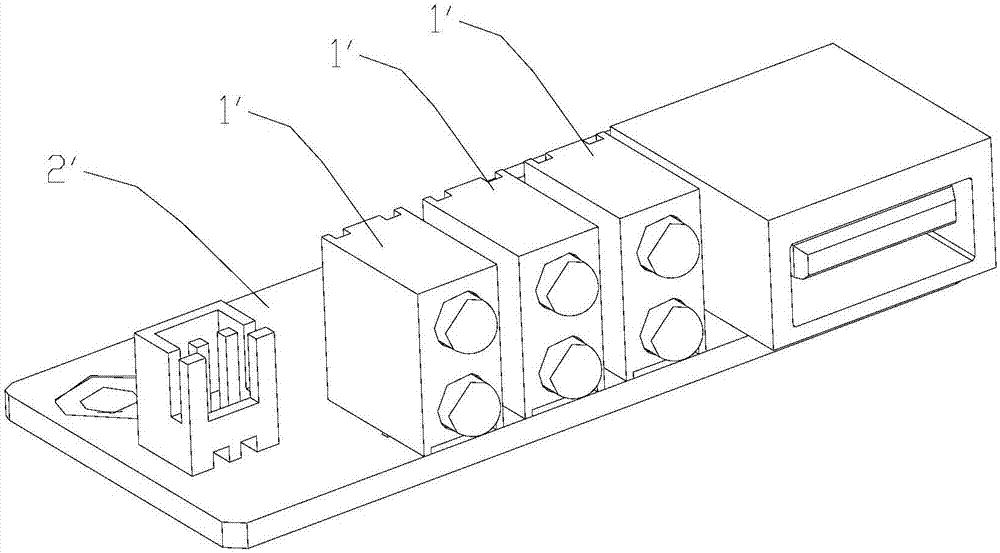
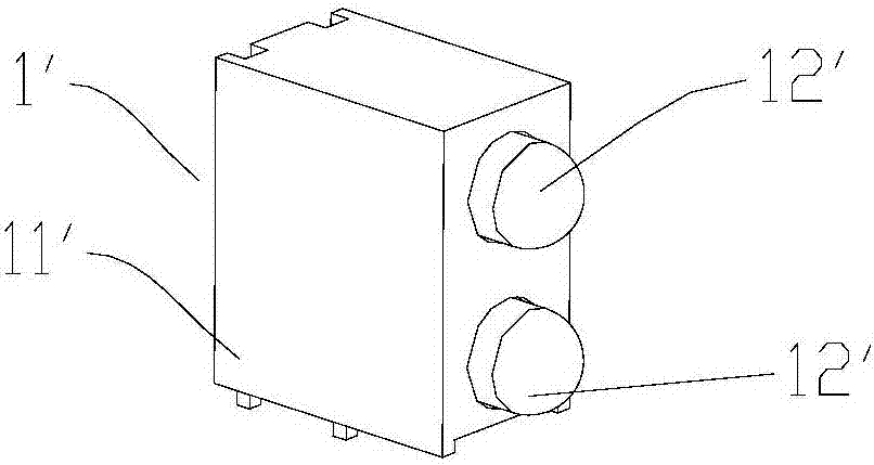
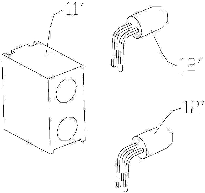
Most of the automotive industry uses LED components 1' to be soldered to PCBA boards 2' (such as figure 1 shown), the LED assembly 1' is composed of a plastic fixing seat 11' and an LED lamp 12' (such as Figure 2-3 ), the general LED assembly 1' needs to manually bend the lamp pin of the LED lamp 12' into a 90-degree angle before welding, and then insert it into the plastic fixing seat 11', and then go through wave soldering. In addition to the increase in labor costs, the LED lamp 12' also has many defects such as unevenness, front and back, etc. When fixing two or more LED lights 12' that are very close to each other on the plastic fixing seat 11', it is easy to affect the prompting signal effect due to flashing light, and it needs to be re-installed manually. Adjust to use

Method used


Image

  • Light guiding device and board clamping device
  • Light guiding device and board clamping device
  • Light guiding device and board clamping device

Examples


Embodiment Construction

[0032] In order to make the purpose, technical solution and advantages of the present application clearer, the present application will be further described in detail below in conjunction with the accompanying drawings and embodiments. It should be understood that the specific embodiments described here are only used to explain the present application, and are not intended to limit the present application.

[0033] It should be noted that when an element is referred to as being “fixed on” or “disposed on” another element, it can be directly on the other element or there may be an intervening element at the same time. When an element is referred to as being "connected to" another element, it can be directly connected to the other element or intervening elements may also be present.

[0034] Such as Figure 4-5 As shown, the light guide device 1 provided by the embodiment of the present application includes a transparent member 11 and a non-transparent member 12 wrapping the tr...


PUM


Abstract

The invention provides a light guiding device and a board clamping device, wherein the light guiding device (1) comprises a transparent component and a non-transparent component that wraps the transparent component. The transparent component is provided with at least two light guiding parts (111). The adjacent two light guiding parts (111) are separated from the non-transparent component (12). The non-transparent component (12) is provided with first through holes (121) corresponding to the light incident side of the light guiding parts (111) respectively and second through holes corresponding to the light outgoing side of the light guiding parts respectively. The light incident sides of the light guiding parts (111) are on the same side, and the light outgoing sides of the light guiding parts are on the same side. The board clamping device comprises a PCBA board clamp. The PCBA board clamp is provided with a light source and the above mentioned light guiding device (1). The light source corresponds to the light incident sides of the light guiding parts (111) respectively. The devices of the invention are simple in structure and convenient in installation. The light from the various light sources are guided and emitted from corresponding light guiding parts, which reduces the light attenuation and the light mixing, therefore, strengthening the prompting effect.

Description

technical field [0001] The invention belongs to the field of signal indicator lights, and in particular relates to a light guide device and a board device. Background technique [0002] LED lights are an important part of the machine as a reminder signal of various functional states of the vehicle monitoring equipment. Most of the automotive industry uses LED components 1' to be soldered to PCBA boards 2' (such as figure 1 shown), the LED assembly 1' is composed of a plastic fixing seat 11' and an LED lamp 12' (such as Figure 2-3 ), the general LED component 1' needs to manually bend the lamp pin of the LED lamp 12' into a 90-degree angle before welding, and then put it into the plastic fixing seat 11', and then go through wave soldering. In addition to the increase in labor costs, the LED lamp 12' also has many defects such as unevenness, front and back, etc. When fixing two or more LED lights 12' that are very close to each other on the plastic fixing seat 11', it is ea...

Claims


Application Information

Patent Timeline
IPC IPC(8): F21K9/61F21V17/16G02B6/00F21Y115/10
CPCF21K9/61F21V17/164F21Y2115/10G02B6/0001
Inventor 罗屹
Owner SHENZHEN STREAMING VIDEO TECH
Learn More