Switching device

A switch, switch contact technology, applied in electrical switches, circuit breaker contacts, switch status indication, etc., can solve problems such as fire, electronic equipment failure, total loss, etc., to reduce materials, reduce material costs, and reduce resource consumption Effect

A switch, switch contact technology, applied in electrical switches, circuit breaker contacts, switch status indication, etc., can solve problems such as fire, electronic equipment failure, total loss, etc., to reduce materials, reduce material costs, and reduce resource consumption Effect

CN107112152AInactive Publication Date: 2017-08-29EATON IND (AUSTRIA) GMBH

Image

  • Switching device
  • Switching device
  • Switching device

Examples


Embodiment Construction

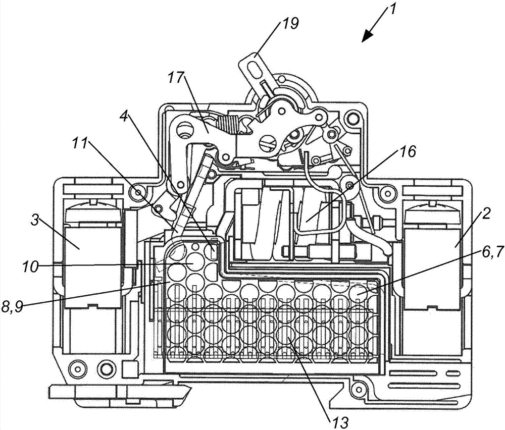
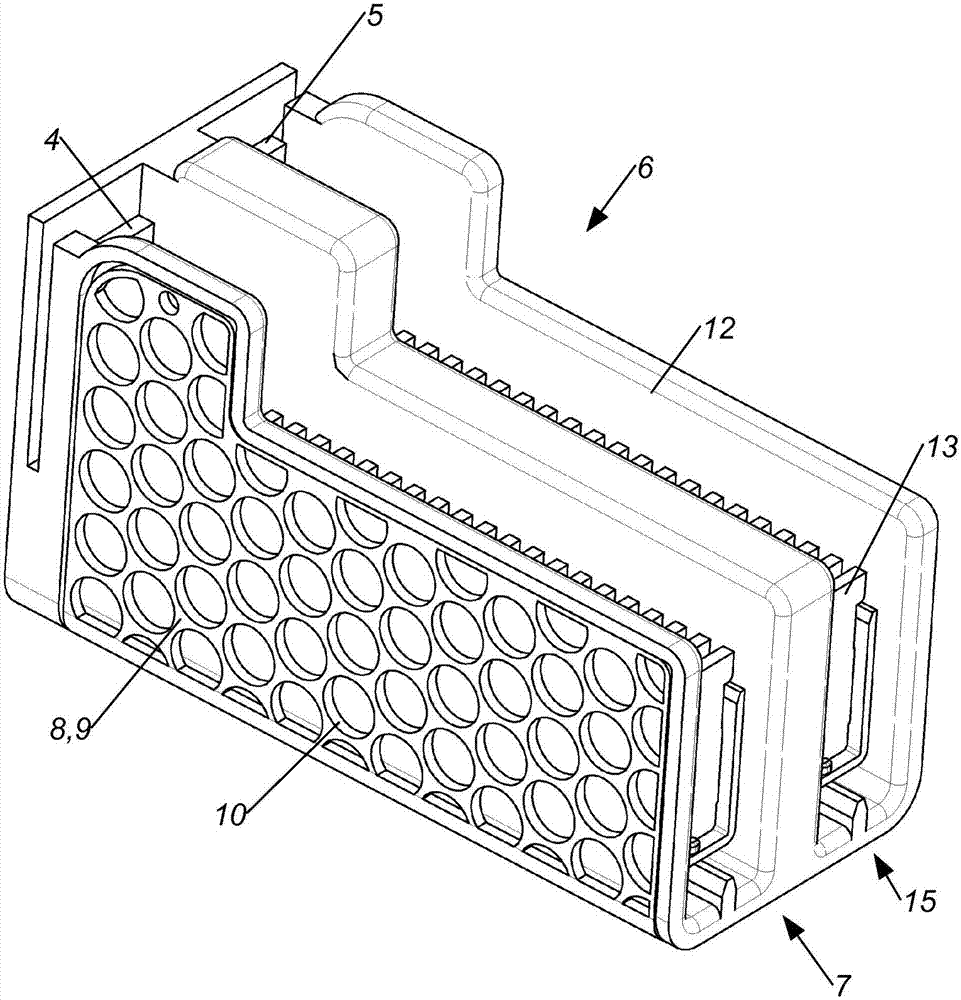
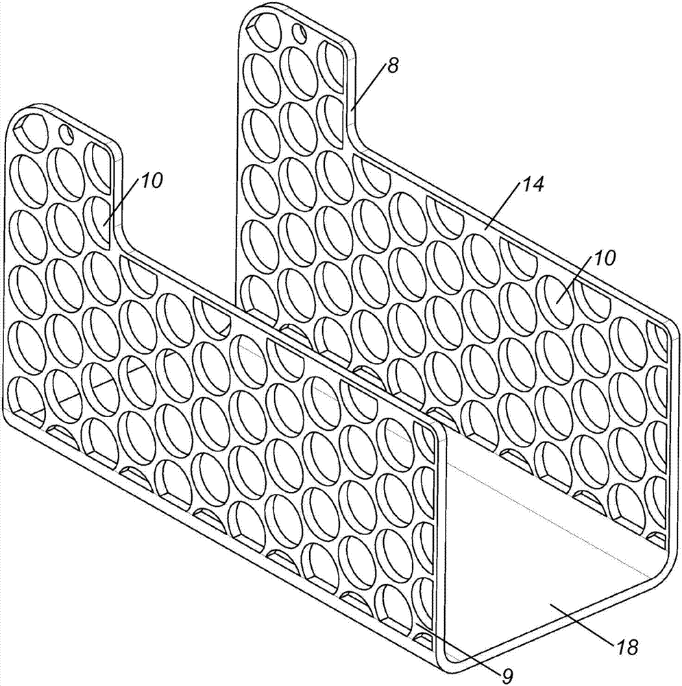
[0013] figure 1 There is shown at least one electrical input 2 and at least one electrical output 3, and at least one first switch contact 4, a second switch contact 5 and a movable jumper 11, wherein if the first switch contact 4 and the second switch contact 5 are electrically conductively connected by means of a jumper wire 11, so that the current path from the input 2 to the output 3 is electrically conductive, wherein the switch 1 also has an arc quenching device 6 with at least one arc quenching chamber 7, Here, a U-shaped iron yoke 8 is arranged partially from the outside around the at least one arc extinguishing chamber 7 , wherein at least one limb 9 of the U-shaped iron yoke 8 has a plurality of predeterminable cutouts 10 .

[0014] It is thus possible to visually detect the effects that actually occur in the quenching device 6 during the disconnection process. By using such a switch as a research or development tool, it is possible to create a direct current switch...


PUM


Abstract

In a switching device (1), in particular a D.C. switching device, with at least one electric input (2) and at least one electric output (3), at least one first switching contact (4) and a movable switching bridge (11), the switching device (1) further having an arc-extinguishing arrangement (6) with at least one arc-extinguishing chamber (7) and a U-shaped yoke (8) arranged around the outside of portions of the at least one arc-extinguishing chamber (7), at least one first limb (9) of the U-shaped yoke (8) has a predeterminable number of passages (10).

Description

technical field [0001] The invention relates to a switch according to the preamble of patent claim 1 . Background technique [0002] Switches are known, in particular for switching on direct current. Special phenomena occur when switching on direct current that are not taken into account in the same form when switching on alternating current. However, the use of direct current has generally been limited to a small power range for a long time, in which case there are few problems when switching on direct current. [0003] Since solar photovoltaics and powerful battery backup systems are widely used in EDV-servers, it is also necessary to switch on higher voltage and power direct current. Here, the known AC switches have proven to be unsuitable in many respects. For example switching on direct current by means of an alternating current switch may result in its total loss even if the voltage and current are well below the maximum alternating current-power limit of the releva...

Claims


Application Information

Patent Timeline
29 Aug 2017
Publication
CN107112152A
IPC
H01H9/34; H01H73/18; H01H9/36; H01H71/04; H01H73/04; H01H73/12
CPC
H01H9/346; H01H9/362; H01H71/04; H01H73/045; H01H73/12; H01H73/18
Inventors
J·柯本斯坦纳