Fan wheel structure

A fan wheel and fan technology, which is applied in the field of fan wheel structure, can solve the problems of uneven load on the wheel hub and easy breakage at the joint.

Active Publication Date: 2017-09-01
ASIA VITAL COMPONENTS SHENZHEN CO LTD
View PDF6 Cites 2 Cited by
  • Summary
  • Abstract
  • Description
  • Claims
  • Application Information

AI Technical Summary

Problems solved by technology

[0007] Another object of the present invention is to provide a fan wheel structure in which the fan blade is combined with the cover, and the cover is combined with the hub to avoid the use of welding to improve the problem of uneven load on the hub.
[0008] Another object of the present inven...

Method used


Image

  • Fan wheel structure
  • Fan wheel structure
  • Fan wheel structure

Examples


Embodiment Construction

[0062] The above-mentioned purpose of the present invention and its structural and functional characteristics will be described based on the preferred embodiments of the accompanying drawings.

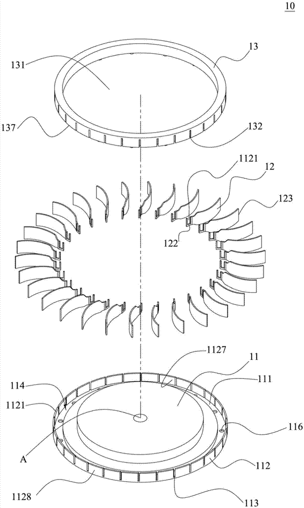
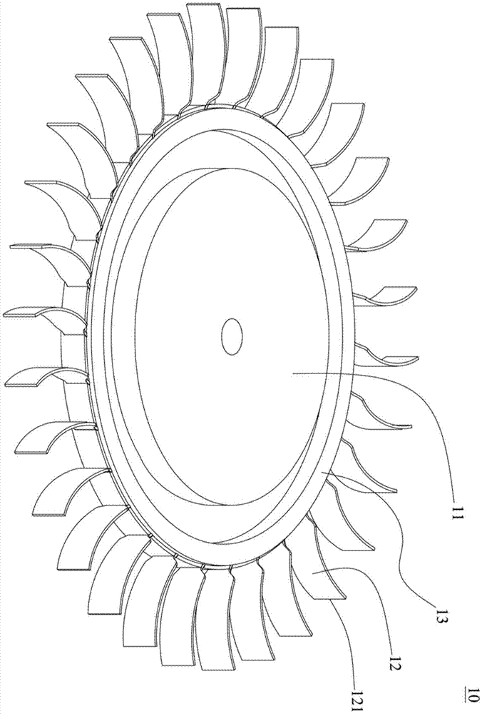
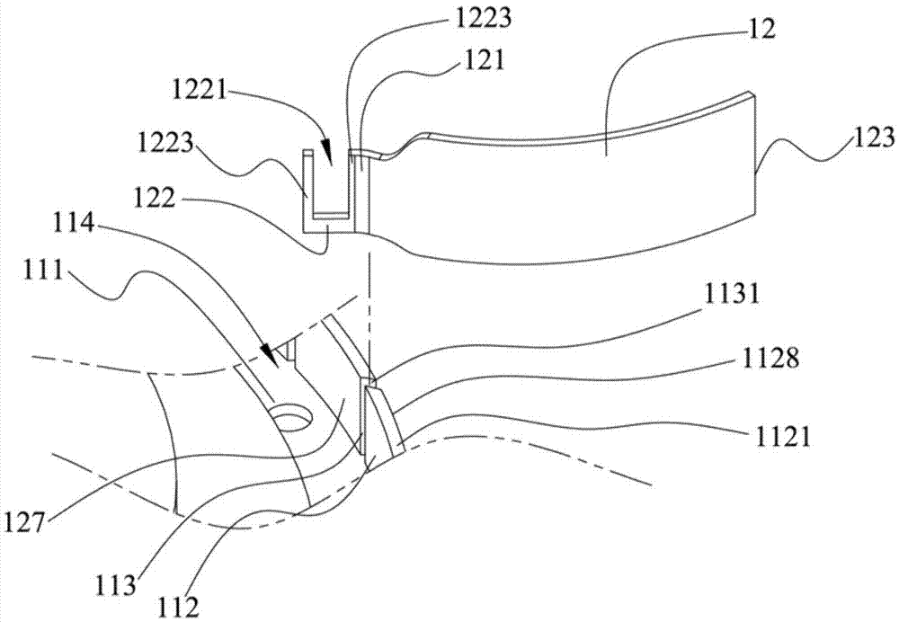
[0063] Figure 1A It is a three-dimensional exploded schematic diagram of the present invention; Figure 1B It is a schematic diagram of the three-dimensional combination of the present invention; Figure 2A It is a schematic diagram of the corresponding relationship between the side wall and the fan blade of the hub of the present invention; Figure 2B It is a schematic diagram of the slot where the fan blade of the present invention is inserted into the side wall of the hub; Figure 3A It is a three-dimensional schematic diagram of another viewing angle of the cover body of the present invention; Figure 3B It is a schematic diagram of the corresponding relationship between the cover body and the fan blade in the present invention. As shown in the figure, the fan wheel structure 1...


PUM


Abstract

The invention provides a fan wheel structure. The fan wheel structure comprises a cover body connected with a plurality of fan blades, and the cover body is arranged on a hub. The hub is provided with a top surface and an accommodating space defined on the top surface, each fan blade is provided with a combining end protruding in the accommodating space, the cover body is provided with a butt joint side and a plurality of combining grooves, the butt joint side is combined with the top surface of the hub, and the combining grooves are arranged around the cover body and separately combined with the combining ends of the fan blades so as to fix the fan blades.

Description

[0001] 【Technical field】 [0002] The invention relates to a cooling element, in particular to a fan wheel structure. [0003] 【Background technique】 [0004] The fan is a common part in the field of electronic heat dissipation. It is usually made of metal or plastic. When the fan blade is made of plastic, it is made by injection molding. Therefore, the fan blade has a certain thickness usually greater than 0.3mm. It should not be too thin, so as not to break the fan blade due to the wind resistance when rotating. Therefore, reduce the thickness of the fan blade to make it an ultra-thin fan blade with considerable strength, and how to combine the ultra-thin fan blade with the hub of the fan, and how to avoid increasing the number of ultra-thin fan blades to cause uneven load on the hub The problem is that the industry needs to work hard at present. [0005] 【Content of invention】 [0006] In order to effectively solve the above problems, one object of the present invention i...

Claims


Application Information

Patent Timeline
IPC IPC(8): F04D29/28
CPCF04D29/282
Inventor 徐亮华王得中
Owner ASIA VITAL COMPONENTS SHENZHEN CO LTD
Why Eureka
Try Eureka