Eureka AIR delivers breakthrough ideas for toughest innovation challenges, trusted by R&D personnel around the world.

Opening frame structure and refrigerating device

A technology for refrigeration equipment and mouth frames, which is applied to household refrigeration devices, lighting and heating equipment, household appliances, etc., can solve problems such as affecting the appearance of the appearance panel 10', affecting the overall appearance of the mouth frame structure, affecting the appearance of the mouth frame structure, and the like, Achieve the effect of improving appearance quality, reducing production costs and reducing materials used

Active Publication Date: 2017-09-01
HEFEI MIDEA REFRIGERATOR CO LTD +2
View PDF8 Cites 2 Cited by
  • Summary
  • Abstract
  • Description
  • Claims
  • Application Information

AI Technical Summary

Problems solved by technology

[0002] At present, during the injection molding process of the existing mouth frame structure, the connection between the rib and the appearance panel will shrink, and then there will be potholes on the outer surface of the appearance panel, which will seriously affect the overall appearance of the mouth frame structure. The shrinkage is more serious in the case of panel thickness
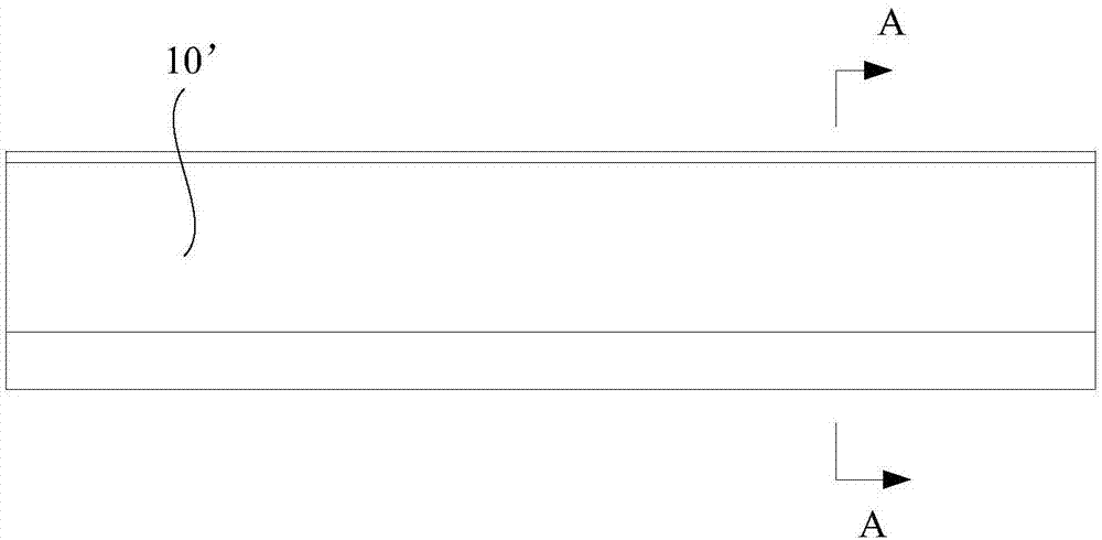
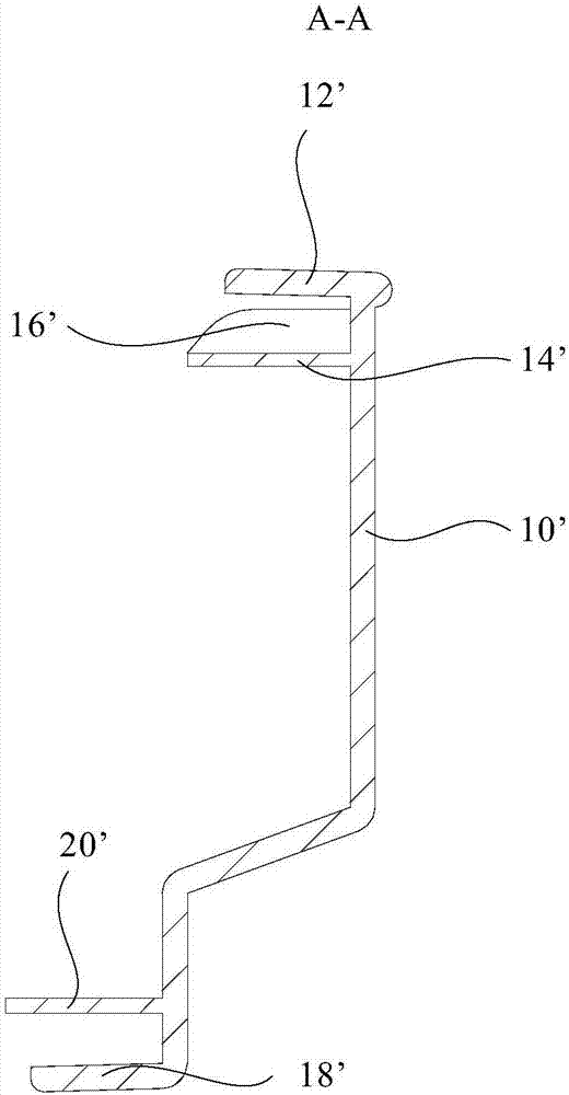
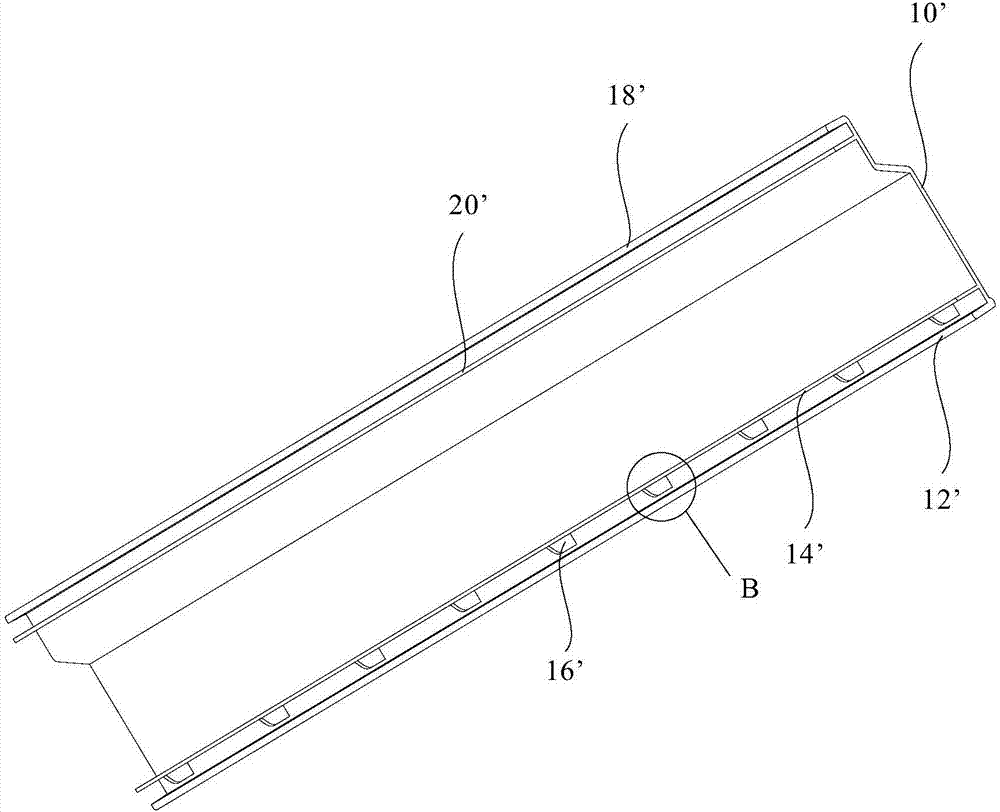
like Figure 1 to Figure 4 As shown, the existing mouth frame structure includes: an appearance panel 10', a first side plate 12', a first rib 14', a short rib 16', a second side plate 18' and a second rib 20', Shrinkage will occur at the connection between the first rib 14' and the appearance panel 10', and the connection between the second rib 20' and the appearance panel 10', causing the appearance panel 10' to sag toward its inner side, affecting the appearance of the panel. 10' appearance, which in turn affects the appearance of the mouth frame structure

Method used


Image

  • Opening frame structure and refrigerating device
  • Opening frame structure and refrigerating device
  • Opening frame structure and refrigerating device

Examples


Embodiment Construction

[0044] In order to understand the above-mentioned purpose, features and advantages of the present invention more clearly, the present invention will be further described in detail below in conjunction with the accompanying drawings and specific embodiments. It should be noted that, in the case of no conflict, the embodiments of the present application and the features in the embodiments can be combined with each other.

[0045] In the following description, many specific details are set forth in order to fully understand the present invention, but the present invention can also be implemented in other ways different from those described here, therefore, the protection scope of the present invention is not limited to the specific details disclosed below. EXAMPLE LIMITATIONS.

[0046] Refer below Figure 5 to Figure 9 Mouth frame structures according to some embodiments of the invention are described.

[0047] like Figure 5 to Figure 9 As shown, according to the embodiment o...


PUM


Abstract

The invention provides an opening frame structure used for a refrigerating device. The refrigerating device comprises a box body. The opening frame structure is arranged at the opening end of the box body and comprises an appearance panel and a first reinforcing rib. A first side plate is arranged on the side, opposite to the outer portion of the box body, of the appearance panel. An arc protrusion is arranged at the position, at the connecting position of the first side plate and the appearance panel, on the outer surface of the appearance panel. The first reinforcing rib is arranged on the inner surface of the appearance panel, and a first insertion groove is formed by the first reinforcing rib and the first side plate. A transition section is arranged at the portion, between the connecting position of the first reinforcing rib and the appearance panel and the arc protrusion, on the outer surface of the appearance panel. The transition section covers the connecting position of the first reinforcing rib and the appearance panel. By means of the opening frame structure and the refrigerating device, due to the fact that the connecting position between the first reinforcing rib and the appearance panel is covered with the transition section, vision transfer can be caused, the problem that the connecting position shrunk in the injection molding process, and consequently the appearance panel is not attractive is effectively avoided, and the appearance quality of the opening frame structure is improved.

Description

technical field [0001] The invention belongs to the technical field of refrigeration equipment, and in particular relates to a mouth frame structure and refrigeration equipment. Background technique [0002] At present, during the injection molding process of the existing mouth frame structure, the connection between the rib and the appearance panel will shrink, and then there will be potholes on the outer surface of the appearance panel, which will seriously affect the overall appearance of the mouth frame structure. In the case of panel thickness, the shrinkage is more serious. like Figure 1 to Figure 4 As shown, the existing mouth frame structure includes: an appearance panel 10', a first side plate 12', a first rib 14', a short rib 16', a second side plate 18' and a second rib 20', Shrinkage will occur at the connection between the first rib 14' and the appearance panel 10', and the connection between the second reinforcement rib 20' and the appearance panel 10', causi...

Claims


Application Information

Patent Timeline
Patent Type & Authority Applications(China)
IPC IPC(8): F25D23/10
CPCF25D23/10
Inventor 夏超
Owner HEFEI MIDEA REFRIGERATOR CO LTD
Why Eureka
Eureka Blog
Learn More