Ventilation detection equipment for textiles

A testing equipment and ventilation technology, applied in the direction of measuring devices, instruments, mechanical devices, etc., can solve the problems of difficulty in comprehensively testing the ventilation of textiles, inability to give full play to the ventilation, and inability to freely adjust the wind power.

Inactive Publication Date: 2017-09-01
孙加红
View PDF10 Cites 9 Cited by
  • Summary
  • Abstract
  • Description
  • Claims
  • Application Information

AI Technical Summary

Problems solved by technology

The air permeability of textiles is particularly important for the production of suitable clothes. However, most of the existing textile testing equipment is difficult to fully detect the air permeability of textiles everywhere, resulting in the inability to fully utilize the characteristics of different degrees of air permeability textiles, and at the same time cannot freely Adjust the size of the wind to meet the needs of testing the ultimate air permeability of textiles
[0004] To sum up, it is necessary to develop a textile air permeability testing equipment that comprehensively detects air permeability and freely adjusts the wind force to overcome the shortcomings of incomplete air permeability detection and difficulty in adjusting the wind force in the prior art.

Method used


Image

  • Ventilation detection equipment for textiles
  • Ventilation detection equipment for textiles
  • Ventilation detection equipment for textiles

Examples


Embodiment 1

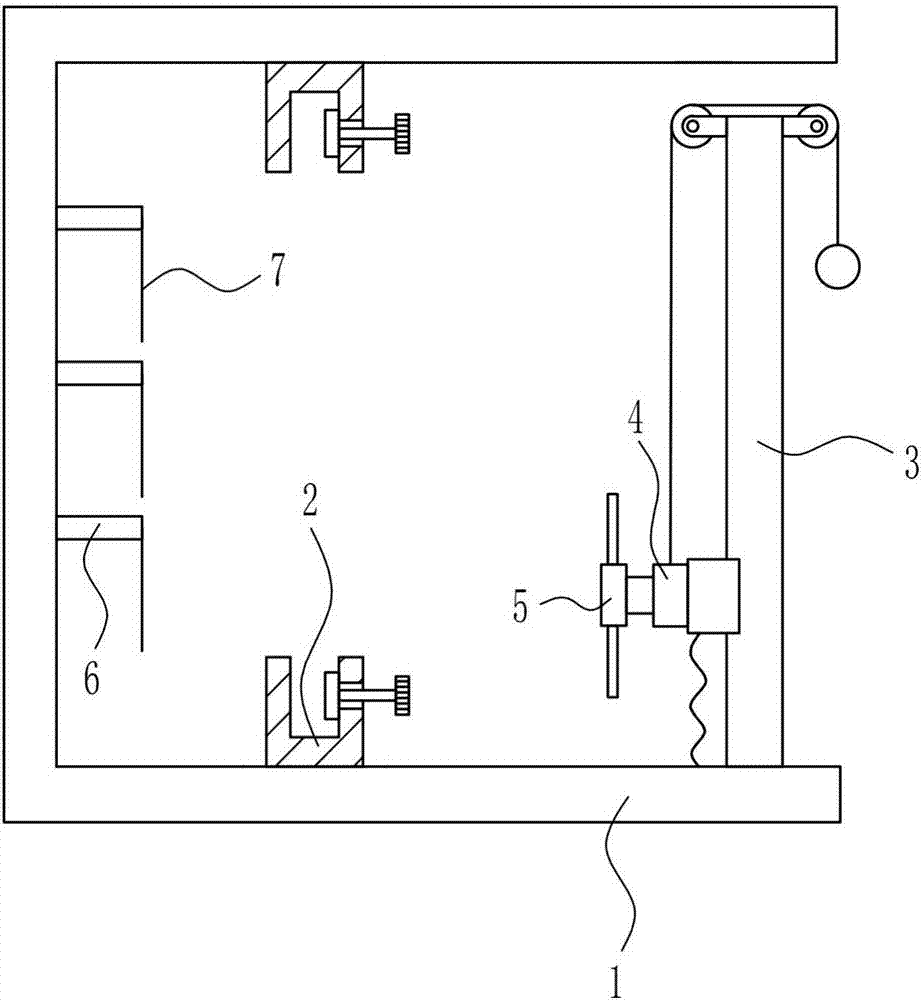
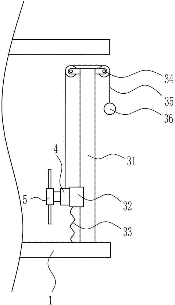
[0031] A textile air permeability detection equipment, such as Figure 1-6 As shown, it includes a mounting frame 1, a fixing device 2, a lifting device 3, a motor 4, a fan 5, a connecting rod 6 and a string 7, and the left side of the inner bottom of the mounting frame 1 and the left side of the inner top of the mounting frame 1 are provided with fixed Device 2, the right side of the inner bottom of the mounting frame 1 is provided with a lifting device 3, the lower left side of the lifting device 3 is provided with a motor 4, the output shaft on the left side of the motor 4 is connected to a fan 5, and the left wall of the mounting frame 1 is evenly provided with connecting rods up and down 6. A string 7 is connected to the right end of the connecting rod 6 .

Embodiment 2

[0033] A textile air permeability detection equipment, such as Figure 1-6 As shown, it includes a mounting frame 1, a fixing device 2, a lifting device 3, a motor 4, a fan 5, a connecting rod 6 and a string 7, and the left side of the inner bottom of the mounting frame 1 and the left side of the inner top of the mounting frame 1 are provided with fixed Device 2, the right side of the inner bottom of the mounting frame 1 is provided with a lifting device 3, the lower left side of the lifting device 3 is provided with a motor 4, the output shaft on the left side of the motor 4 is connected to a fan 5, and the left wall of the mounting frame 1 is evenly provided with connecting rods up and down 6. A string 7 is connected to the right end of the connecting rod 6 .

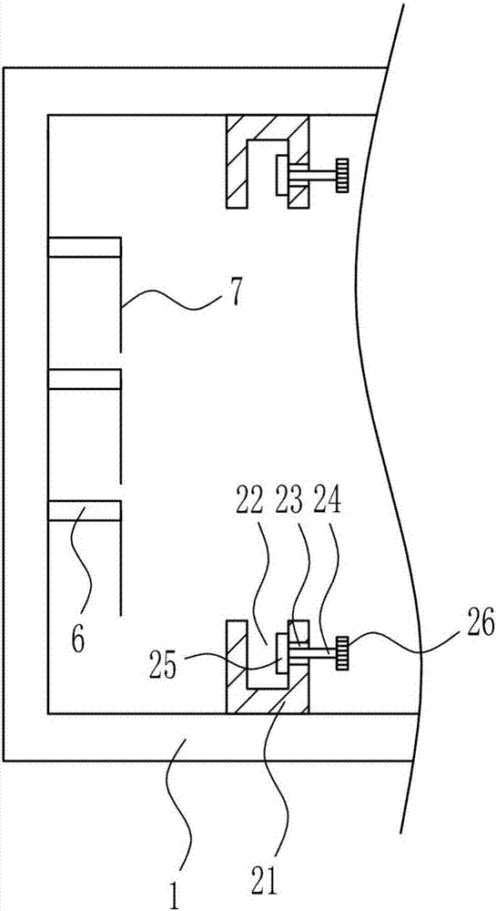
[0034] The fixing device 2 includes a fixing block 21, a bolt 24, a rubber plate 25 and a rubber sleeve 26. The left side of the inner bottom of the mounting frame 1 and the left side of the inner top of the mounting ...

Embodiment 3

[0036] A textile air permeability detection equipment, such as Figure 1-6 As shown, it includes a mounting frame 1, a fixing device 2, a lifting device 3, a motor 4, a fan 5, a connecting rod 6 and a string 7, and the left side of the inner bottom of the mounting frame 1 and the left side of the inner top of the mounting frame 1 are provided with fixed Device 2, the right side of the inner bottom of the mounting frame 1 is provided with a lifting device 3, the lower left side of the lifting device 3 is provided with a motor 4, the output shaft on the left side of the motor 4 is connected to a fan 5, and the left wall of the mounting frame 1 is evenly provided with connecting rods up and down 6. A string 7 is connected to the right end of the connecting rod 6 .

[0037] The fixing device 2 includes a fixing block 21, a bolt 24, a rubber plate 25 and a rubber sleeve 26. The left side of the inner bottom of the mounting frame 1 and the left side of the inner top of the mounting ...


PUM


Abstract

The invention relates to detection equipment and in particular to ventilation detection equipment for textiles, which can be used for detecting ventilation comprehensively and adjusting wind power freely. In order to solve the technical problem, the ventilation detection equipment comprises a mounting rack. Fixing devices are arranged on the left side of the bottom and the left side of the top in the mounting rack, a lifting device is arranged on the right side of the bottom in the mounting rack, a motor is arranged on the lower portion of the left side of the lifting device, an output shaft on the left side of the motor is connected to a fan, connecting rods are uniformly arranged on the left wall in the mounting rack up and down, and fine ropes are connected to the right ends of the connecting rods. By matching a rubber plate with a bolt to fix a textile, ventilation detection for the textile is facilitated; by matching a rubber ball with a guy wire, the position of the fan is conveniently adjusted.

Description

technical field [0001] The invention relates to a detection device, in particular to a textile air permeability detection device. Background technique [0002] The original meaning of textile is taken from the general term of spinning and weaving, but with the continuous development and improvement of the textile knowledge system and subject system, especially after the emergence of non-woven textile materials and three-dimensional composite weaving technologies, the current textile is not only a traditional Hand spinning and weaving also include garment, industrial and decorative textiles produced by non-woven technology, modern three-dimensional weaving technology, and modern electrostatic nano-netting technology. Therefore, modern textile refers to a multi-scale structure processing technology of fibers or fiber aggregates. [0003] Ancient Chinese textile and printing and dyeing technology has a very long history. As early as the primitive society, the ancients knew how...

Claims


Application Information

Patent Timeline
Patent Type & Authority Applications(China)
IPC IPC(8): G01N19/00
CPCG01N19/00
Inventor 孙加红
Owner 孙加红
Why Eureka
Try Eureka