A continuous zoom optical device

A technology of optical devices and optical systems, applied in the field of optical systems, can solve the problems of increased volume and weight of optical devices, unfavorable miniaturization design, etc., and achieve the effect of reducing the entrance pupil distance

Active Publication Date: 2019-07-26
湖北久之洋信息科技有限公司
View PDF4 Cites 0 Cited by
  • Summary
  • Abstract
  • Description
  • Claims
  • Application Information

AI Technical Summary

Problems solved by technology

[0005] like Figure 4 As shown, if the iris diaphragm is placed between the front fixed group and the variable magnification group, the distance between the aperture of the first surface and the entrance pupil of the optical device is the smallest, but the apertures of the compensation group and the rear fixed group increase rapidly. Large, resulting in increased volume and weight of the optical device, which is not conducive to miniaturization design

Method used


Image

  • A continuous zoom optical device
  • A continuous zoom optical device
  • A continuous zoom optical device

Examples


Embodiment 1

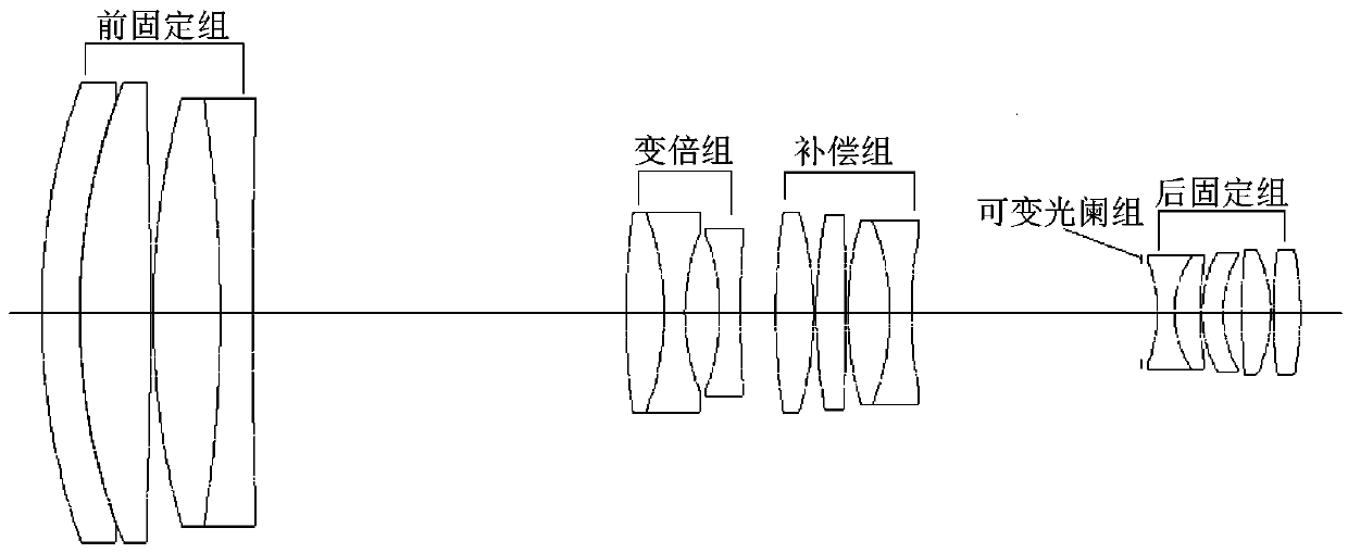
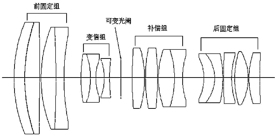
[0023] Such as Figure 5 to Figure 7 As shown, a basic embodiment of a continuous zoom optical device with a small aperture and a large amount of light in the present invention, it includes being installed on the same optical axis O-O, and the total length of the optical system changes accordingly during the process of continuously changing the focal length, and the distance between the image plane 6 Five components that remain unchanged, three moving along the direction of the optical axis, one moving in the direction perpendicular to the optical axis, and one fixed on the optical axis: the five mirror groups take the end of the compensation group 1 where the light enters as the front end , one end of the image plane 6 is the rear end, which are arranged in order from front to back: compensation group 1, zoom group 2, iris group 3, focusing group 4 and rear fixed group 5.

[0024] The compensation group 1 is a positive refractive power group with a dual structure, which is us...

Embodiment 2

[0030] It is a further technical scheme on the basis of embodiment 1.

[0031] The relative aperture D / f of the compensation group 1 is 1 / 1.9, and from the front to the back is: a double cement composed of a high refractive index medium dispersion lanthanum flint positive meniscus lens and a low dispersion low refractive index light crown biconvex lens The lens is a doublet lens composed of a low dispersion low refractive index light crown biconvex lens and a high refractive index high dispersion heavy flint biconcave lens.

[0032] The variable magnification group 2 is as follows from front to back: a doublet lens composed of a high refractive index high dispersion heavy flint biconvex lens and a medium refractive index low dispersion lanthanum crown biconcave lens, and a low dispersion heavy barium flint negative meniscus lens .

[0033] The iris group 3 is located at a fixed position between the zoom group 2 and the focus group 4, and the aperture of the light is variable....


PUM


Abstract

The invention discloses a continuous zoom optical device which comprises a compensation group, a zooming group, a variable diaphragm group, a focusing group, a rear fixation group and an image plane. The compensating group moves in the direction of the optical axis O-O, and is composed of two double glued lenses. The zooming group moves in the direction of the optical axis O-O, and is composed of a double glued lens and a negative meniscus lens. The variable diaphragm group moves perpendicular to the optical axis O-O. The focusing group moves in the direction of the optical axis O-O, and is composed of two biconvex lenses and a double glued lens. The rear fixation group is fixed on the optical axis O-O, and is composed of a biconvex lens and two double glued lenses. According to the invention, the total length is variable, and a compensation curve is an irregular curve shaped like a parabola. Under the same relative aperture condition, the continuous zoom optical device has the advantages that the optical aperture is reduced by 30% and the entrance pupil distance is reduced by 25.7 % compared with an optical device with invariable total length.

Description

technical field [0001] The invention belongs to the technical field of optical systems, and in particular relates to a continuous zoom optical device with a small aperture and a large amount of light, which is suitable for concealed observation of a target in a periscope state. Background technique [0002] In the periscope state, in order to observe the target on the water surface that requires a field of view and operating distance, and at the same time have good concealment, it is required that the part of the observation equipment exposed to the water surface should be as small as possible. figure 1 The schematic diagram of the structure of the existing periscope equipment is shown, that is, when the size of the protective glass is fixed, to meet the requirements of the field of view and the operating distance, the aperture of the light must be reduced as much as possible under the premise of ensuring that the relative aperture of the optical device remains unchanged and...

Claims


Application Information

Patent Timeline
Patent Type & Authority Patents(China)
IPC IPC(8): G02B15/17
CPCG02B15/17
Inventor 罗劲峰郭良贤程子清张泉李颖文胡际先
Owner 湖北久之洋信息科技有限公司
Why Eureka
Try Eureka