Vacuum interrupter bipolar compound longitudinal magnetic field contact structure

A technology of vacuum interrupter and longitudinal magnetic field, which is applied in the direction of high-voltage air circuit breakers, electrical components, electric switches, etc., and can solve the problem of loss of breaking ability of vacuum interrupter, vacuum arc cannot be effectively controlled by longitudinal magnetic field, and limited application, etc. problems, to achieve the effect of improving the control ability of the longitudinal magnetic field, improving the breaking ability of large current, and the conducting ability of high rated current

Active Publication Date: 2017-09-01
XI AN JIAOTONG UNIV
View PDF5 Cites 2 Cited by
  • Summary
  • Abstract
  • Description
  • Claims
  • Application Information

AI Technical Summary

Problems solved by technology

However, there is a longitudinal magnetic field in the horseshoe-type longitudinal magnetic contacts of the vacuum interrupter to effectively control the longest arcing distance of the vacuum arc, that is, as the distance between the contacts increases, the longitudinal magnetic field between the contacts decreases continuously, and when When the contact opening distance exceeds a certain value, the vacuum arc cannot be effectively controlled by the longitudinal magnetic field, resulting in the loss of the breaking ability of the vacuum interrupter
The above-mentioned characteristics of the horseshoe-shaped longitudinal magnetic contact limit its application in high-voltage, large-opening vacuum interrupters

Method used


Image

  • Vacuum interrupter bipolar compound longitudinal magnetic field contact structure
  • Vacuum interrupter bipolar compound longitudinal magnetic field contact structure
  • Vacuum interrupter bipolar compound longitudinal magnetic field contact structure

Examples


Embodiment Construction

[0019] Embodiments of the present invention will be further described in detail below in conjunction with the accompanying drawings.

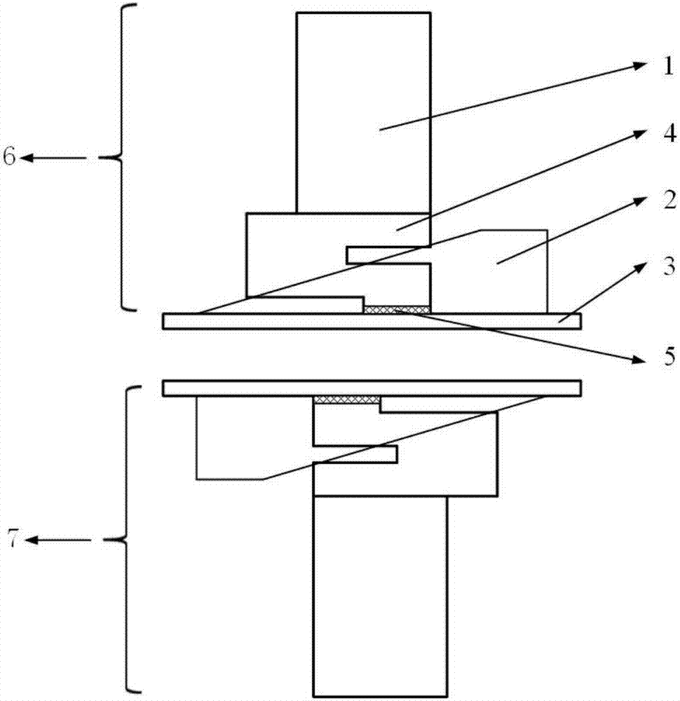
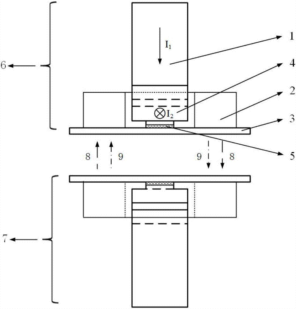
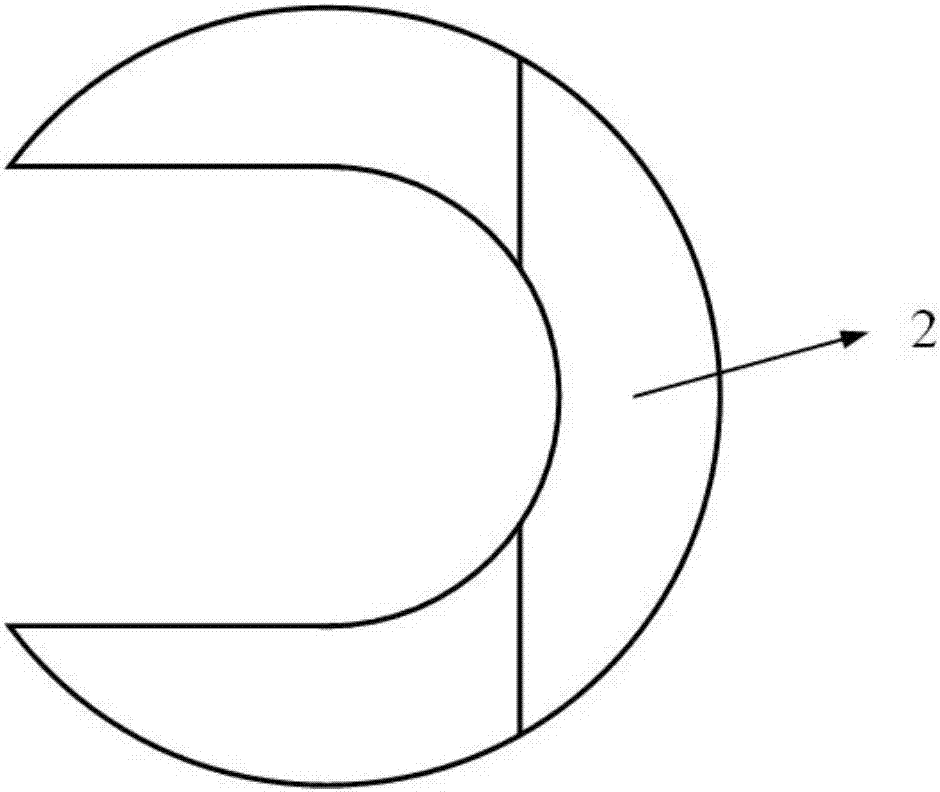
[0020] figure 1 It is a schematic diagram of the bipolar compound longitudinal magnetic field contact structure of the present invention, including an anode contact system 6 and a cathode contact system 7, both of which have the same structure and are arranged in a vacuum interrupter. Both the anode contact system 6 and the cathode contact system 7 include a conductive circuit and a magnetic circuit, and the conductive circuit is composed of a conductive rod 1, a contact piece 3 and a flow guide structure 4; the magnetic circuit is composed of a magnetic structure 2 composition. The magnetically conductive structure 2 with one side opening is arranged on the back of the contact piece 3 , the conductive rod 1 is connected to the contact piece 3 through the current guiding structure 4 , and passes through the opening of the magnetically conducti...


PUM


Abstract

The invention provides a vacuum interrupter bipolar compound longitudinal magnetic field contact structure. The structure comprises an anode contact system and a cathode contact system, wherein the anode contact system and the cathode contact system are arranged in a vacuum interrupter. The anode contact system comprises a contact sheet and a magnetic conductive structure which is arranged on the back of the contact sheet and is provided with an opening on the single side. A conductive rod is connected with the contact sheet through a diversion structure and passes through the opening of the magnetic conductive structure. The diversion structure, the magnetic conductive structure and the contact sheet are fixed by welding. The cathode contact system and the anode contact system share the same structure. The contact sheets are oppositely arranged, and the opening direction of the magnetic conductive structure is opposite. The conductive rod, the contact sheets and the diversion structure form a conductive circuit. The magnetic conductive structure forms a magnetic conductive circuit. According to the structure provided by the invention, the longitudinal magnetic field strength in the vacuum interrupter can be improved; a strong longitudinal magnetic field area is increased; the longitudinal magnetic field of the existing vacuum interrupter is increased; the maximum arcing distance of vacuum arc is effectively improved; and the vacuum interrupter circuit resistance is low.

Description

technical field [0001] The invention belongs to the technical field of vacuum switches, and in particular relates to a bipolar compound longitudinal magnetic field contact structure of a vacuum interrupter. Background technique [0002] High-voltage vacuum circuit breaker is an important switchgear in power system because of its advantages of small size, simple structure, environment-friendly and maintenance-free. At present, in order to improve the breaking capability of the high-voltage vacuum interrupter, the vacuum arc is usually controlled by applying a magnetic field in the vacuum interrupter. In addition, in order to increase the rated current level of the high-voltage vacuum circuit breaker, it is necessary to reduce the loop resistance of the conductive part of the vacuum interrupter. In the prior art, a horseshoe-shaped longitudinal magnetic contact can effectively reduce the circuit resistance of the vacuum interrupter, and at the same time provide a strong longi...

Claims


Application Information

Patent Timeline
Patent Type & Authority Applications(China)
IPC IPC(8): H01H33/664
CPCH01H33/664
Inventor 王建华李昊旻王子寒耿英三刘志远
Owner XI AN JIAOTONG UNIV
Why Eureka
Try Eureka