
A longitudinal magnetic contact for vacuum interrupter based on ferromagnetic material

A technology of vacuum interrupter and ferromagnetic material, which is applied to high-voltage air circuit breakers, high-voltage/high-current switches, electrical components, etc., can solve the problems of limited DC vacuum arc control and small residual magnetic field, and is conducive to rapid Diffusion, small residual magnetic field in the gap, and the effect of reducing agglomeration

Active Publication Date: 2021-11-09
HUAZHONG UNIV OF SCI & TECH
View PDF0 Cites 0 Cited by
  • Summary
  • Abstract
  • Description
  • Claims
  • Application Information

AI Technical Summary

Problems solved by technology

[0005] Aiming at the deficiencies of the existing cup-shaped longitudinal magnetic contacts, the present invention provides a ferromagnetic material-based vacuum interrupter longitudinal magnetic contact, aiming to solve the bell-shaped distribution caused by the cup-shaped longitudinal magnetic contacts in the prior art. In the longitudinal magnetic field, the diffusion of the arc in the initial stage of arcing is dominated by the inhibition effect, which leads to the problem that the control effect on the DC vacuum arc is limited; the purpose of the present invention is to make it longitudinally The magnetic field intensity is greater than the central area, and the longitudinal magnetic field distribution is relatively uniform when the opening distance is large, and the residual magnetic field is small after the current crosses zero

Method used


Image

  • A longitudinal magnetic contact for vacuum interrupter based on ferromagnetic material
  • A longitudinal magnetic contact for vacuum interrupter based on ferromagnetic material
  • A longitudinal magnetic contact for vacuum interrupter based on ferromagnetic material

Examples


Embodiment Construction

[0027] In order to make the objectives, technical solutions and advantages of the present invention clearer, the present invention will be further described in detail below with reference to the accompanying drawings and specific embodiments. It should be understood that the specific embodiments described herein are only used to explain the present invention, but not to limit the present invention.

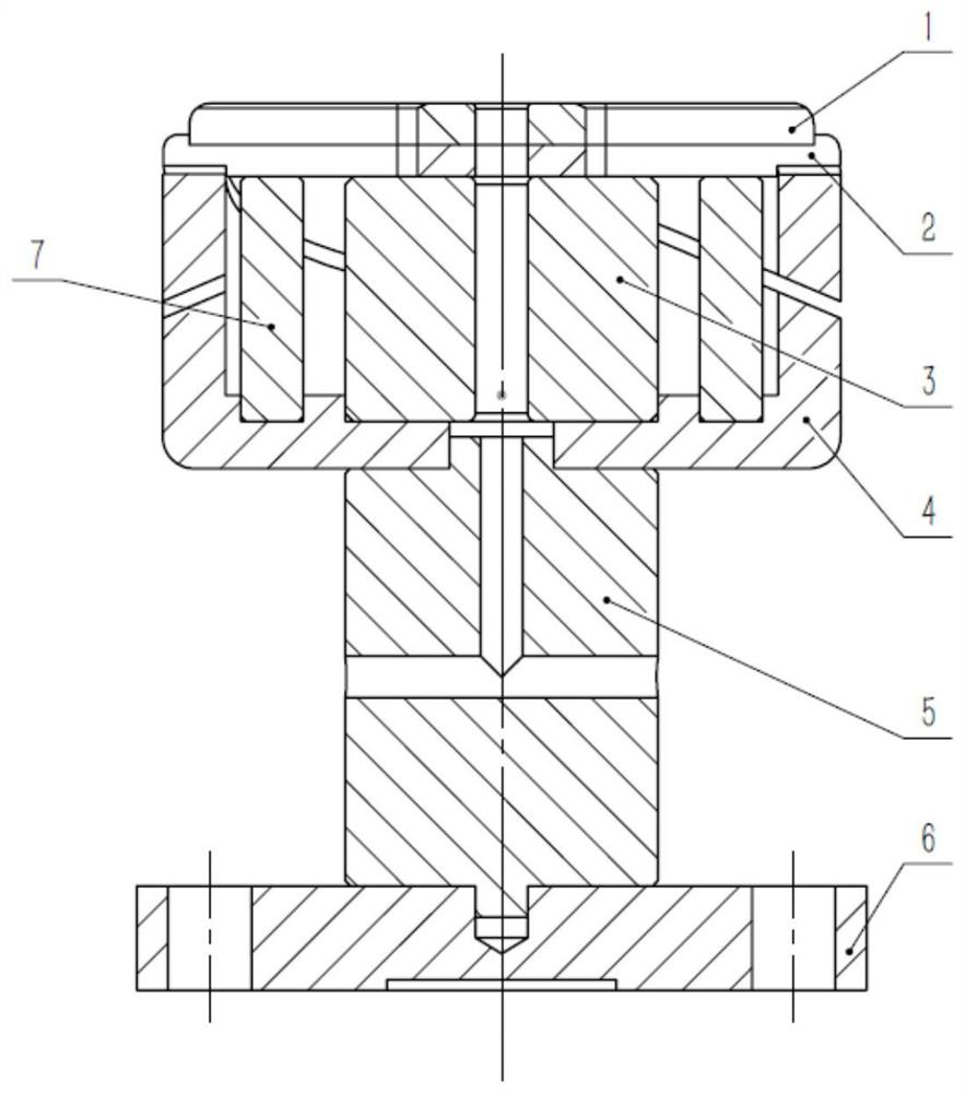
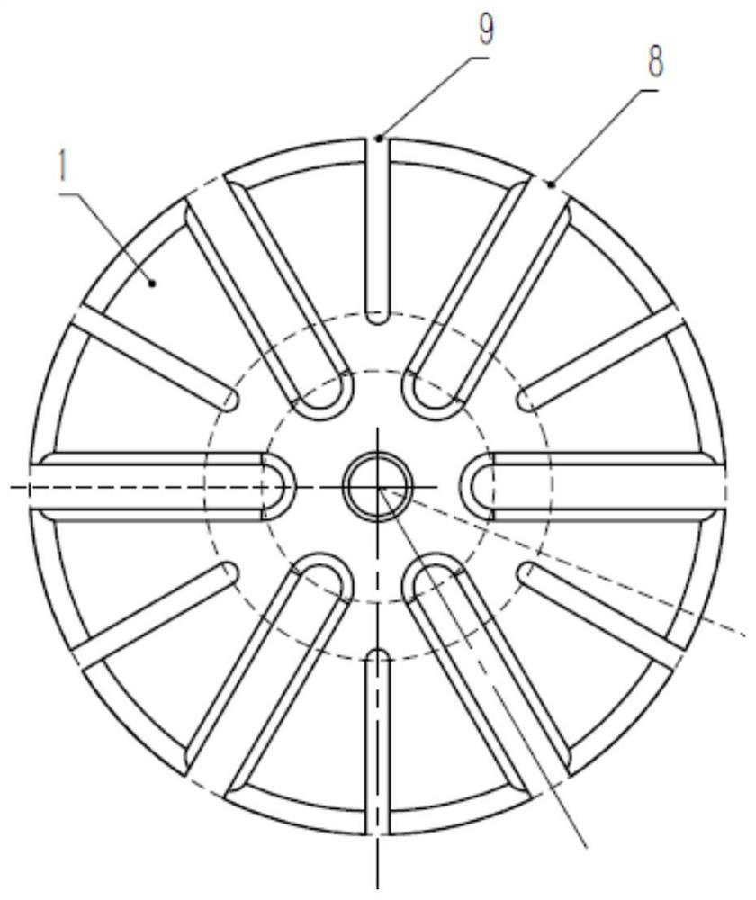
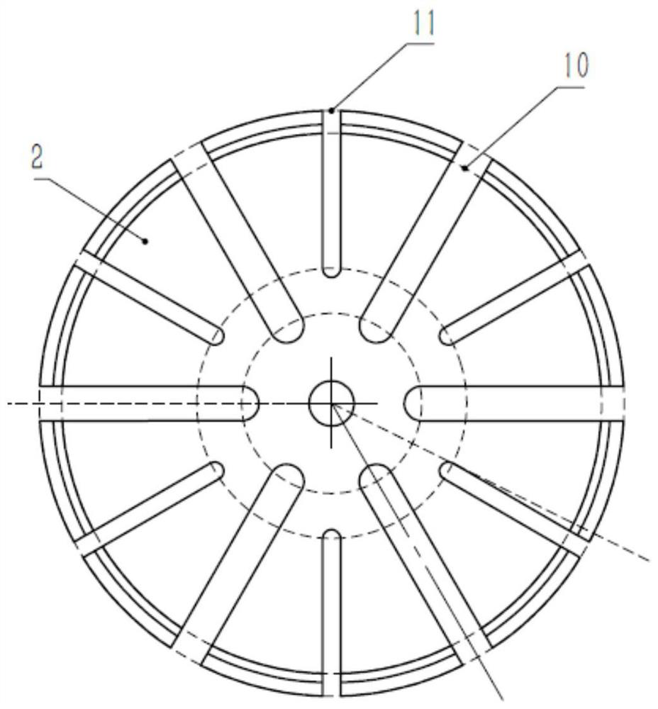
[0028] like figure 1 As shown, the core components of the longitudinal magnetic contact of the vacuum interrupter based on ferromagnetic materials include a contact piece 1, a contact holder 2, a support frame 3, a contact cup 4, a conductive rod 5, a backing ring 6 and a ferromagnetic column 7. The material of the contact piece 1 is CuCr50, which is widely used in the high-voltage vacuum interrupter, that is, the mass fraction of Cu and Cr both account for 50%, which can take into account the needs of the contact in terms of higher electrical conductivity and mechanical strength....


PUM

PropertyMeasurementUnit
electrical conductivityaaaaaaaaaa

Abstract

The invention discloses a longitudinal magnetic contact of a vacuum interrupter based on a ferromagnetic material, comprising a contact piece, a contact holder, a contact cup, a support frame, a ferromagnetic column and a conductive rod; the contact piece and the contact holder There are radial grooves evenly on the top, half of which are large grooves and half of which are small grooves; the grooves on the contact cup rotate 90° along the cup wall to form cup fingers; the support frame is fixed in the center of the cup cavity and mainly plays a supporting role ; The cylindrical ferromagnetic material is fixed between the support frame and the inner wall of the contact cup, and is distributed near the notch of the contact cup. contact with the lower surface. The contact structure can improve the magnetic field distribution of the cup-shaped longitudinal magnetic contact in the vacuum interrupter. When the opening distance is small, the longitudinal magnetic field intensity at the edge of the contact is greater than that in the central area. When the opening distance is large, the longitudinal magnetic field distribution is relatively uniform. The magnetic field is small, and it has the advantages of strong breaking capacity, high strength and simple structure.

Description

technical field [0001] The invention belongs to the technical field of vacuum interrupters, and more particularly, relates to a longitudinal magnetic contact of a vacuum interrupter based on ferromagnetic materials. Background technique [0002] In the HVDC transmission system, the DC circuit breaker, as an important control and protection device, is the guarantee for the safe and reliable power supply of the HVDC transmission system. Among them, the vacuum interrupter is the key element for arc generation and extinguishing, and its breaking performance is closely related to the contact structure used. [0003] HVDC transmission system has the characteristics of fast rising speed of fault current and no natural zero-crossing point, which is the main obstacle restricting the development of HVDC transmission technology. The DC circuit breaker based on the artificial zero-crossing principle generates a high-frequency reverse current through the commutation branch and superimpo...

Claims


Application Information

Patent Timeline
Patent Type & Authority Patents(China)
IPC IPC(8): H01H33/664
CPCH01H33/6642
Inventor 袁召何俊磊潘垣陈立学
Owner HUAZHONG UNIV OF SCI & TECH
Learn More