
Lead overhead apparatus

A technology of lead wires and wire clamps, which is applied in the direction of overhead lines/cable equipment, etc., can solve the problems that the distance between two adjacent wire clamps is not easy to determine, reduce labor intensity, and easily fall off, etc., achieve good locking effect of lead wires and reduce labor intensity , The effect of convenient loading and unloading

Active Publication Date: 2017-09-01
STATE GRID ZHEJIANG ELECTRIC POWER CO LTD QUZHOU POWER SUPPLY CO +3
View PDF4 Cites 2 Cited by
  • Summary
  • Abstract
  • Description
  • Claims
  • Application Information

AI Technical Summary

Problems solved by technology

[0004] The invention overcomes the problems that only one wire clip can be loaded and unloaded at a time during the lapping operation of live wires, the distance between two adjacent wire clips is not easy to determine, the wire clips are inconvenient to install and disassemble, the labor intensity is high, the lead wire overhead operation is time-consuming and laborious, and the lead wire locking effect Insufficient that it is easy to cause the risk of falling off, a lead wire overhead device is provided, and two wire clips can be loaded and unloaded at one time during the lapping operation of the lead wire in live work. The labor intensity is greatly reduced, the overhead operation of the lead wire is more time-saving and labor-saving, and the lead wire locking effect is good without the risk of falling off

Method used


Image

  • Lead overhead apparatus
  • Lead overhead apparatus
  • Lead overhead apparatus

Examples


Embodiment

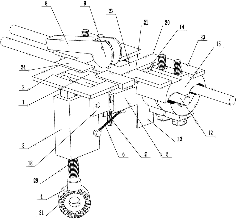
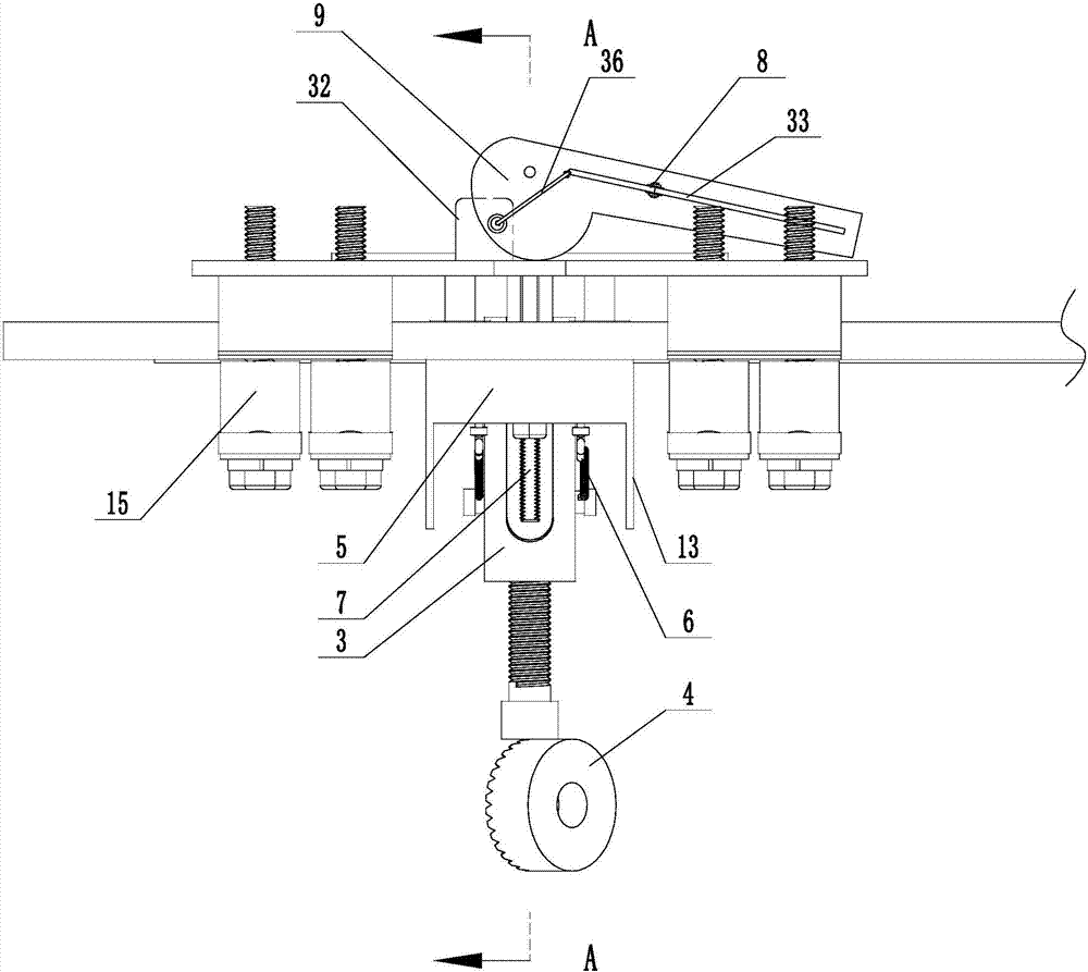
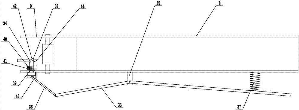
[0023] Embodiment: a kind of lead wire overhead device (see attached Figures 1 to 5), including a fixed splint 1, a push splint 2, a mounting seat 3 connected to the fixed splint, an insulating rod connector 4 connected to the mounting seat, the push splint can be slidably installed on the fixed splint, and a press seat 5 is rotatably connected to the mounting seat. The return spring 6 is connected between the seat and the mounting seat, the locking rod 7 is connected to the pressure seat, the locking rod runs through the fixed splint, the end of the locking rod is rotated and connected to the handle 8, and an eccentric lock is provided on the handle and the connecting end of the locking rod. The tight disk 9, the eccentric locking disk abuts against the fixed splint, and a limit locking mechanism is connected between the eccentric locking disk and the fixed splint. The cross-section of the handle is a rectangular frame structure, two eccentric locking discs are arranged oppo...


PUM


Abstract

The invention discloses a lead overhead apparatus, and aims to overcome the shortcomings that only one wire clamp can be assembled or disassembled in one time in an electrified operation lead lap joint operation and it is not easy to determine the distance between adjacent two wire clamps, and the shortcomings of inconvenient assembling and disassembling of the wire clamp, high labor intensity, time consumption and labor consumption in the lead overhead operation, poor lead locking effect and risk of easy falling off. The lead overhead apparatus comprises a fixed clamping plate and a push clamping plate; the fixed clamping plate is connected with a mounting base; the mounting base is rotationally connected with a pressing base; the pressing base is connected with a locking rod; the end part of the locking rod is rotationally connected with a handle; eccentric locking plates are arranged at the connecting end between the handle and the locking rod; each eccentric locking plate tightly props against the fixed clamping plate; a locking clamping groove is formed in the pressing base; a plurality of pressing plates are arranged in the positions, opposite to the locking clamping groove, of the fixed clamping plate; a lead is mounted between the pressing plates and the locking clamping groove; a positioning and clamping groove used for mounting and clamping a wire clamp is formed between the push clamping plate and the fixed clamping plate and on each of the two sides of the pressing base; the wire clamp is mounted in each positioning and clamping groove; and the wire clamp is connected with the lead.

Description

technical field [0001] This invention relates to power operated tools and, more particularly, to a lead wire overhead device. Background technique [0002] At present, live work projects mainly focus on lapping and removing lead wires. Among them, the operation technology of lapping lead wires by insulating rod operation method is very difficult and requires high professional quality of staff. In addition to skilled technology and strong safety awareness, operators must Must also be in good physical condition. Insulation rod operation method Live lap lead wire operation is a common operation, and the labor intensity is relatively high, especially when the foot buckles are used to climb the pole, the arms, waist, and cervical spine are stressed for a long time, and the operators are prone to fatigue. The tightening seat between the locking bolt and the cable clamp is easy to rotate during the rotation and locking process of the fastening bolt on the wire clamp, and it is nec...

Claims


Application Information

Patent Timeline
IPC IPC(8): H02G1/02
CPCH02G1/02
Inventor 姜小军郑晓军胡仁杰余星临赵宁严威表王天明华建亮周旺翌吴海宝陈博文赵慧生陆承东郑湘君
Owner STATE GRID ZHEJIANG ELECTRIC POWER CO LTD QUZHOU POWER SUPPLY CO
Learn More