Charging method and charging system of mobile robot

A mobile robot and charging method technology, which is applied in the field of mobile robots, can solve the problems of long time to find a charging seat, deviation of laser scanning code alignment, etc., and achieve the effect of rapid recharging and high alignment accuracy.

Pending Publication Date: 2017-09-01
SHEN ZHEN 3IROBOTICS CO LTD
View PDF1 Cites 28 Cited by
  • Summary
  • Abstract
  • Description
  • Claims
  • Application Information

AI Technical Summary

Problems solved by technology

The recharging solution based on infrared positioning takes a long time to find the charging seat when the mobile robot is recharging a

Method used


Image

  • Charging method and charging system of mobile robot
  • Charging method and charging system of mobile robot
  • Charging method and charging system of mobile robot

Examples


Embodiment 1

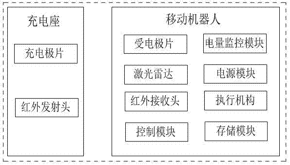
[0027] Such as figure 2 As shown, the charging system of the mobile robot of the present invention includes a charging base and a mobile robot, wherein the charging base includes a charging pole piece and an infrared emitting head, and the mobile robot includes a receiving electrode piece, a laser radar, an infrared receiving head, a control module, a storage module, Power module, power monitoring module and actuator. The receiving electrode sheet is used to contact the charging electrode sheet of the charging stand for power supply, the lidar is used for real-time positioning and map creation (ie SLAM), and the infrared receiving head is used to receive the infrared emission from the charging stand signal (the infrared receiving head in this embodiment includes two receiving heads, left and right, and the infrared emitting head of the charging stand also includes two infrared emitting heads, left and right), the control module is used to The feedback information sends instr...

Embodiment 2

[0038] Such as image 3 As shown, the charging system of the mobile robot of the present invention includes a charging base and a mobile robot, wherein the charging base includes a charging pole piece, an infrared emitting head and a characteristic mark (including a bar code or a two-dimensional code), and the mobile robot includes a receiving electrode piece, a laser radar , an infrared receiving head, a control module, a storage module, a power supply module, a power monitoring module and an actuator. The receiving electrode sheet is used to contact the charging electrode sheet of the charging stand for power supply, the lidar is used for real-time positioning and map creation (ie SLAM) and scanning the characteristic marks of the charging stand, and the infrared receiving head is used to receive The signal sent by the infrared transmitter of the charging stand, the control module is used to send instructions to the actuator according to the information fed back by the laser...


PUM


Abstract

The invention discloses a charging method of a mobile robot. The charging method comprises the following steps of S1, detecting a charging seat by a laser radar or an infrared signal when the mobile robot is in a non charging-back state; S2, adding position information of the mobile robot when the charging seat is detected or position information of the charging seat into a map by the mobile robot; S3, seeking a position of the charging seat by the mobile robot according to the map; and S4, achieving aligned charging-back with the charging seat by the mobile robot according to an infrared charging-back signal. The position information of the mobile robot or the position information of the charging seat when the charging signal is detected is added into the map, the charging seat is sought according to the map information when charging-back is required by the mobile robot, the mobile robot can be rapidly navigated to a part near to the charging seat, alignment is performed by an infrared positioning mode, and the charging method has the advantages of rapid charging-back and high alignment accuracy. Moreover, the invention also discloses a charging system of the mobile robot.

Description

technical field [0001] The invention relates to mobile robot technology, in particular to a charging method and a charging system for a mobile robot. Background technique [0002] With the development of science and technology, mobile robots can be used in various occasions to replace manpower to complete various tasks. Work, efficiently complete various tasks in an effective space and time, and is currently widely used in logistics, detection, service and other fields. [0003] Existing mobile robots generally use rechargeable batteries to provide power, and the continuous power supply time that rechargeable batteries can provide is relatively short, and the general running time exceeds 2 or 3 hours, and it needs to be charged. How to design a reasonable recharging algorithm to make the mobile robot complete automatic recharging when the battery is insufficient has become one of the challenges that the mobile robot faces. [0004] At present, the automatic recharging sche...

Claims


Application Information

Patent Timeline
IPC IPC(8): H02J7/00H02J50/30H02J50/90
CPCH02J7/025Y02B40/00
Inventor 杨勇杨庆辉吴泽晓李崇国
Owner SHEN ZHEN 3IROBOTICS CO LTD
Why Eureka
Try Eureka