Visible light channel joint balance method based on orthogonal mapping and probabilistic neural network

A probabilistic neural network and joint equalization technology, which is applied in the field of visible light communication, can solve problems such as a large amount of calculation, and achieve the effect of improving reliability and suppressing interference

Active Publication Date: 2017-09-01
SUN YAT SEN UNIV
View PDF4 Cites 19 Cited by
  • Summary
  • Abstract
  • Description
  • Claims
  • Application Information

AI Technical Summary

Problems solved by technology

However, neural network training requires a large amount of calculation, which is a great...

Method used


Image

  • Visible light channel joint balance method based on orthogonal mapping and probabilistic neural network
  • Visible light channel joint balance method based on orthogonal mapping and probabilistic neural network
  • Visible light channel joint balance method based on orthogonal mapping and probabilistic neural network

Examples


Embodiment 1

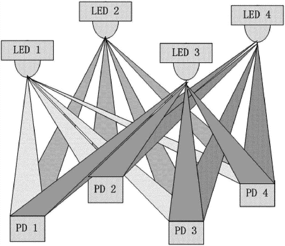
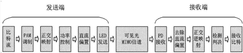
[0050] A visible light channel joint equalization method based on orthogonal mapping and probabilistic neural network, including a transmitting end and a receiving end, and a signal is transmitted from the transmitting end to the receiving end through a visible light MIMO channel; the visible light MIMO channel is a multiple-input multiple-output channel; Described joint equalization is the combination of pre-equalization and post-equalization; its method comprises the following steps: figure 2 :

[0051] sender:

[0052] S1: generate bit stream;

[0053] S2: perform signal modulation on the bit stream;

[0054] S3: Carry out orthogonal vector mapping on the modulated signal;

[0055] S4: performing power control on the new modulated signal obtained after orthogonal vector mapping;

[0056] S5: Add a DC bias to the output signal so that all values ​​are non-negative;

[0057] S6: The LED converts the electrical signal into an optical signal and sends it to the visible li...

Embodiment 2

[0071] The focus of this embodiment is to suppress interference between MIMO channels. Literature [4] pointed out that due to the existence of multipath effects in traditional RF transmission systems, there will be intersymbol interference (Inter Symbol Interference, ISI), but compared with traditional RF channels, the root mean square (Root Mean Square) caused by multipath effects Square, RMS) delay spread is much smaller than the RF channel, so the inter-symbol interference in the time domain is not considered for the time being.

[0072] Suppose the number of senders is N t , the number of receivers is Nr, and the visible light MIMO channel matrix is ​​Nr times N t Two-dimensional matrix H.

[0073] The sender first generates N t Road N-bit 0 1 signal B, Then perform 2-PAM modulation on B to obtain the signal and in Modulated information sent for the i-th channel. Carry out orthogonal vector mapping on the modulated signal A. The specific implementation method i...


PUM


Abstract

The invention discloses a visible light channel joint balance method based on orthogonal mapping and a probabilistic neural network. The method comprises a transmitting end and a receiving end. Signals are transmitted from the transmitting end to the receiving end through visible light MIMO (Multiple Input Multiple Output) channels. The visible light MIMO channels are multiple input multiple output channels. According to joint balance, preposition balance and postposition balance are combined. According to the method, a joint balance scheme combing a preposition balance technology and a postposition balance technology is employed, namely, the visible light multiple input multiple output channel joint balance method based on the orthogonal mapping and the probabilistic neural network is employed. The interference between the channels of a visible light MIMO communication system can be effectively suppressed and the data transmission reliability is improved.

Description

technical field [0001] The present invention relates to the visible light communication field of mobile communication, and more specifically, relates to a visible light channel joint equalization method based on orthogonal mapping and probabilistic neural network. Background technique [0002] In recent years, with the development and promotion of light-emitting diodes (Light-emitting Diode, LED), visible light communication (Visible Light Communications, VLC) has also become popular due to its outstanding advantages (clean, high security, rich spectrum resources, etc.) It has attracted the attention of many scholars [1]. At the same time, VLC has become a potentially strong candidate to address the explosive growth of access devices due to its ability to transmit at high speeds over short distances. [0003] The modulation bandwidth of existing commercial LEDs is limited (about 10-20 MHz), which limits the transmission rate of visible light communication using LEDs as tran...

Claims


Application Information

Patent Timeline
IPC IPC(8): H04L25/03H04B7/0413H04B10/116
CPCH04B7/0413H04B10/116H04L25/03006H04L25/03165H04L25/03343
Inventor 潘纪言张琳
Owner SUN YAT SEN UNIV
Why Eureka
Try Eureka