Automatic variable diameter device of reinforcement cage (skeleton) seam welder

A technology of rolling welding machine and steel cage, which is applied in the direction of roller electrode welding, welding equipment, resistance welding equipment, etc., can solve the problems of complicated equipment fabrication and installation, long time for changing type, and small diameter change range. To achieve the effect of shortening the replacement time, simple and convenient maintenance and maintenance, and convenient operation

Active Publication Date: 2017-09-05
YICHANG HAITIAN ULTRASONIC TECH
View PDF7 Cites 2 Cited by
  • Summary
  • Abstract
  • Description
  • Claims
  • Application Information

AI Technical Summary

Problems solved by technology

At present, most of the steel cages for electric poles are manufactured by hand. In addition to the slow speed and high labor cost, the quality of the production is also low, especially the uneven distribution of the winding bars and the out-of-round shape of the main bars restrict the manufacturing process. Important factors for quality poles
Some mechanical equipment adopts gear transmission on the variable diameter device, which makes the production and installation of the equipment more complicated, and the range of variable diameter is small, and it takes a long time to change the type.

Method used


Image

  • Automatic variable diameter device of reinforcement cage (skeleton) seam welder
  • Automatic variable diameter device of reinforcement cage (skeleton) seam welder
  • Automatic variable diameter device of reinforcement cage (skeleton) seam welder

Examples


Embodiment Construction

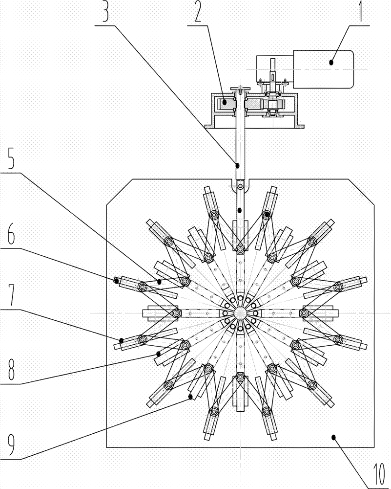
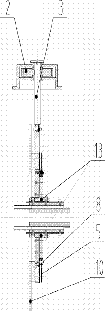
[0027] Such as figure 1 , figure 2 As shown, a diameter reducing device of a steel cage roll welding machine includes a mounting plate 10 and a plurality of first limiting devices 8 evenly arranged with point P on the mounting plate 10 as the center of the circle, and the first limiting devices 8 slide The moving position of guide rod 9 is limited. Preferably, the first position limiting device 8 is a sliding sleeve with two open ends, and the sliding guide rod 9 penetrates from one end of the sliding sleeve and passes out from the other end. The sliding guide rod 9 reciprocates along the straight line from the point P to the center point of the first limiting device 8;

[0028] A second limiting device 7 is arranged between adjacent two first limiting devices 8, and the second limiting device 7 limits the moving position of the transition guide rod 6. Preferably, the second limiting device 7 is a two-terminal Open sliding sleeve, the transition guide rod 6 penetrates from ...


PUM


Abstract

A variable diameter device of a reinforcement cage seam welder comprises a mounting plate and a plurality of first limiting devices uniformly arranged with the P point of a mounting plate being as the circle center. The first limiting devices limit the movement positions of sliding guide rods. A second limiting device is arranged between every two adjacent first limiting devices. The second limiting devices limit the movement positions of transition guide rods. Each slide guide rod is connected with the two corresponding transition guide rods adjacent to the slide guide rod through two connecting rods. The portions, located at the movement positions of the slide guide rods and / or the transition guide rods, of the mounting plate are provided with open grooves. The slide guide rods and / or the transition guide rods are provided with electrode bracket assemblies which comprise electrode brackets. Guide pipes penetrate through the middles of the electrode brackets. Connecting blocks are connected with the electrode brackets through current conducting plates. The electrode bracket assemblies are connected with the sliding guide rods and / or the transition guide rods through the connecting blocks. The guide pipes are perpendicularly inserted into the open grooves. One or more sliding guide rods or transition guide rods are connected with a gear motor. The variable diameter device has the advantages that through linear movement of a lead screw, the variable diameter is intuitively determined, namely the variable diameter difference value is the displacement of the lead screw, and automatic welding of a conical electric pole and an equal diameter electric pole can be conveniently achieved.

Description

technical field [0001] The invention patent relates to an automatic reducing device for a steel cage (skeleton) roll welding machine, such as automatic welding equipment such as cement poles, pipe pile steel cage (skeleton) roll welders, culvert pipe steel cage (skeleton) roll welders, etc. Background technique [0002] In the transformation and laying of the power grid, a large number of cement poles are needed, and the cement poles are formed by pouring concrete into the steel cage of the pole. At present, most of the steel cages for electric poles are manufactured by hand. In addition to the slow speed and high labor cost, the quality of the production is also low, especially the uneven distribution of the winding bars and the out-of-round shape of the main bars restrict the manufacturing process. An important factor in the quality of poles. Some mechanical equipment adopts gear transmission on the diameter reducing device, which makes the manufacture and installation of...

Claims


Application Information

Patent Timeline
IPC IPC(8): B23K11/06B23K11/36
Inventor 怀义文马志刚怀莲
Owner YICHANG HAITIAN ULTRASONIC TECH
Why Eureka
Try Eureka