
Multifunctional wiring terminal integrating telemetering and telesignalling acquisition

A wiring terminal and multi-functional technology, which is applied in the field of remote signaling and telemetry, can solve the problems of increased maintenance workload of DC transmitter operation reliability, no signal conversion mode of telemetry acquisition terminals, and inability to realize small current, etc., to achieve increased reliability , The effect of reducing the difficulty of installation and reducing the cost

Pending Publication Date: 2022-02-11
GUIZHOU POWER GRID CO LTD
View PDF0 Cites 0 Cited by
  • Summary
  • Abstract
  • Description
  • Claims
  • Application Information

AI Technical Summary

Problems solved by technology

And the telemetry acquisition terminal has no signal conversion method, so it cannot realize small current (such as 4-20mA) or small voltage (0-5V) output. For the general measurement and control device DC board (current type: 4-20mA, voltage type: 0-5V ), the signal volume collected by telemetry (generally the secondary voltage of the voltage transformer or the secondary current of the current transformer) cannot be directly connected to the DC board of the measurement and control device
[0003] The problem caused by this is that if the existing technology collects the analog quantity of a certain remote signaling circuit, it can be realized by using an independent DC transmitter, etc., but there are many problems as follows: one DC transmitter is required for the acquisition object , greatly increasing the cost; the guarantee and maintenance workload of the DC transmitter operation reliability increased; the difficulty of on-site installation and other problems

Method used


Image

  • Multifunctional wiring terminal integrating telemetering and telesignalling acquisition
  • Multifunctional wiring terminal integrating telemetering and telesignalling acquisition
  • Multifunctional wiring terminal integrating telemetering and telesignalling acquisition

Examples


Embodiment 1

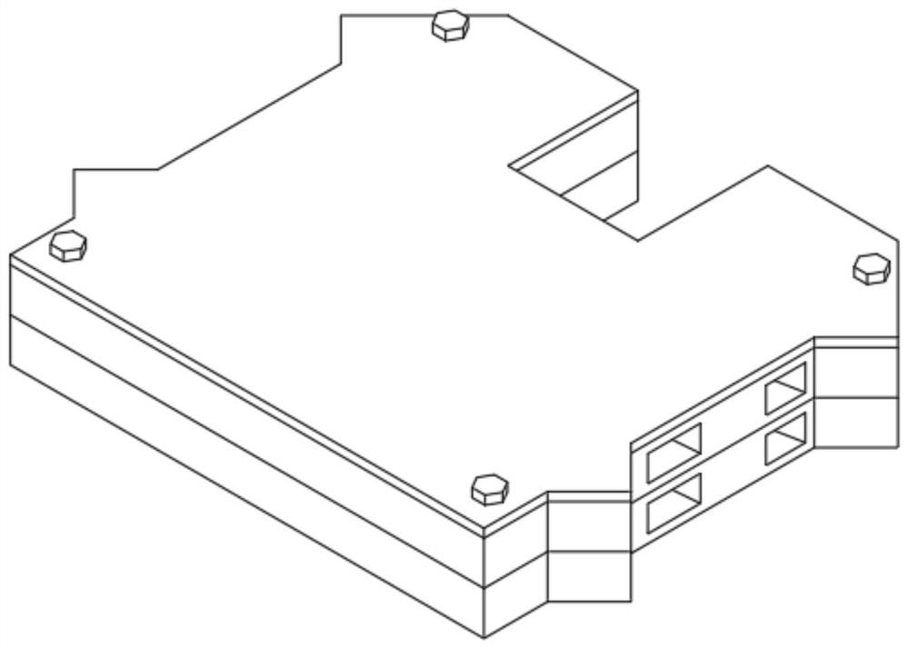
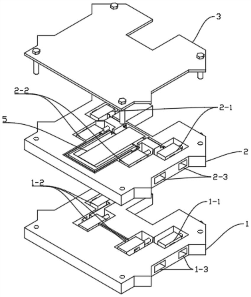
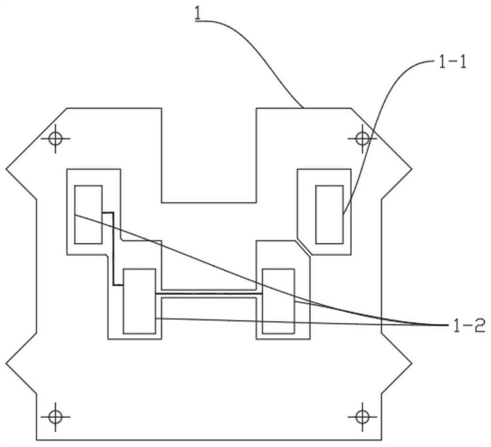
[0035] Implementation Example 1: Reference Figure 1 to Figure 5 , a kind of multi-function connection terminal that collects telemetry and remote signal, comprising: a first remote signal connection terminal 1; a second remote signal connection terminal 2; a voltage conversion circuit 5, and the voltage conversion circuit 5 is arranged on the second remote signal connection terminal On terminal 2, the positive input end of the voltage conversion circuit 5 is connected to the positive crimping wire of the first remote signaling terminal 1, and the negative input end of the voltage conversion circuit 5 is connected to the negative crimping wire of the first remote signaling terminal 1. To connect, the positive output end of the voltage conversion circuit 5 is connected to the positive voltage wire frame wire of the second remote signaling terminal 2, and the negative output end of the voltage conversion circuit 5 is connected to the negative voltage wire frame wire of the second...


PUM


Abstract

The invention discloses a multifunctional wiring terminal integrating telemetering and telesignalling acquisition. The multifunctional wiring terminal comprises a first telesignalling wiring terminal; a second telesignalling wiring terminal; a voltage conversion circuit which is arranged on the second telesignalling wiring terminal, wherein the positive electrode input end of the voltage conversion circuit is electrically connected with the positive electrode wire pressing frame of the first telesignalling wiring terminal, and the negative electrode input end of the voltage conversion circuit is electrically connected with the negative electrode wire pressing frame of the first telesignalling wiring terminal, the positive electrode output end of the voltage conversion circuit is electrically connected with the positive electrode wire pressing frame of the second telesignalling wiring terminal, and the negative electrode output end of the voltage conversion circuit is electrically connected with the negative electrode wire pressing frame of the second telesignalling wiring terminal, wherein the second telesignalling wiring terminal is fixedly connected to the first telesignalling wiring terminal through a bolt. The problems that in the prior art, telesignalling and telemetering signals cannot be collected at the same time, telemetering collected semaphores cannot be directly connected to a measurement and control direct current board, cost is high, maintenance workload is large, and installation is difficult are solved.

Description

technical field [0001] The invention relates to a multifunctional connection terminal integrating remote measurement and remote signal collection, belonging to the technical field of remote signal and telemetry. Background technique [0002] At present, the terminals used in the collection of remote signaling signals and telemetry signals on the market are all independent terminals. And the telemetry acquisition terminal has no signal conversion method, so it cannot realize small current (such as 4-20mA) or small voltage (0-5V) output. For the general measurement and control device DC board (current type: 4-20mA, voltage type: 0-5V ), the signal volume collected by telemetry (generally the secondary voltage of the voltage transformer or the secondary current of the current transformer) cannot be directly connected to the DC board of the measurement and control device. [0003] The problem caused by this is that if the existing technology collects the analog quantity of a ce...

Claims


Application Information

Patent Timeline
IPC IPC(8): G01R1/04G01R31/00
CPCG01R1/04G01R31/00
Inventor 杨成江徐继林滕清松刘汉菁邓牟军倪永健葛振亚田可万毅王旭林王启琼罗万芳谢忠瀚庄著名谭文辉刘伟马庆臣
Owner GUIZHOU POWER GRID CO LTD
Learn More