Liquid supply device, printing apparatus and liquid ejection system

A technology for liquid supply, printing device, applied in the direction of printing, printing device, etc.

Active Publication Date: 2017-09-05
SEIKO EPSON CORP
View PDF16 Cites 8 Cited by
  • Summary
  • Abstract
  • Description
  • Claims
  • Application Information

AI Technical Summary

Problems solved by technology

[0013] In addition, the above-mentioned problem is not limited to the liquid supply device for printers, but is also a problem common to liquid supply devices that supply other types of liquids and liquid ejection devices that use the liquid supply device.

Method used


Image

  • Liquid supply device, printing apparatus and liquid ejection system
  • Liquid supply device, printing apparatus and liquid ejection system
  • Liquid supply device, printing apparatus and liquid ejection system

Examples


no. 1 approach

[0132] A-1. Structure of liquid injection system:

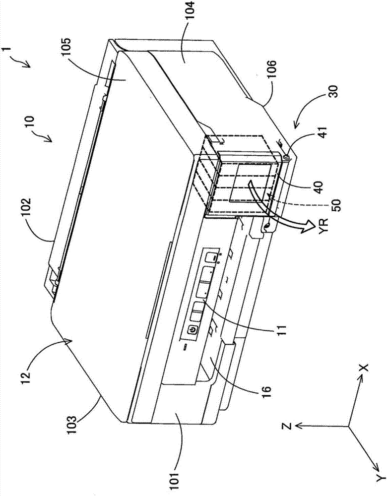
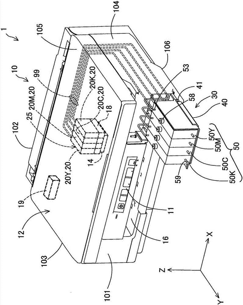
[0133] figure 1 and figure 2 It is a schematic diagram of the liquid ejection system 1 as the first embodiment of the present invention. figure 1 The appearance of the liquid ejection system 1 in use is shown. figure 2 The external appearance and part of the internal structure (dotted line) of the liquid ejection system 1 in the injected state are shown. exist figure 1 and figure 2 There are mutually orthogonal X-axis, Y-axis and Z-axis plotted in . The X-axis corresponds to the “width direction” of the printer 10 . Likewise, the Y axis corresponds to the “depth direction” of the printer 10 , and the Z axis corresponds to the “height direction” of the printer 10 . That is, the printer 10 is installed on a horizontal installation surface defined by the X-axis direction and the Y-axis direction. In addition, in figure 1 and figure 2 Herein, the +Z-axis direction (ie, the upper side of the paper) is also referred t...

no. 2 approach

[0208] Figure 9 It is a diagram conceptually showing a flow path from the atmosphere opening 59 of the liquid supply device 50 a to the liquid outlet 53 according to the second embodiment of the present invention. The liquid supply device 50a of the second embodiment differs from the liquid supply device 50 of the first embodiment in the number of buffer chambers 54a1 to 54a3 and the structure of the atmosphere communication path 56a. The other configurations of the liquid supply device 50 a are the same as those of the liquid supply device 50 , so the same reference numerals are assigned to the same configurations, and description thereof will be omitted.

[0209] In the liquid supply device 50a, three buffer chambers 54a1, 54a2, and 54a3 are provided in series in the middle of the atmosphere communication path 56a. The buffer chamber 54a1, the buffer chamber 54a2, and the buffer chamber 54a3 are arranged in this order from the upstream side toward the downstream side. Her...

no. 3 approach

[0236] D-1. Structure of Liquid Injection System:

[0237] Figure 11 as well as Figure 12 It is a schematic diagram of a liquid ejection system 1m as a third embodiment of the present invention. Figure 11 Indicates the appearance of the liquid injection system 1m, Figure 12 The external appearance and a part of the internal structure (dotted line) of the liquid ejection system 1m are shown. The liquid ejection system 1 m includes a printer 10 m, a liquid storage unit 30 m including a liquid storage chamber 50 m, and an air storage chamber 60 m. The printer 10m functions as a "liquid ejecting device". The liquid storage unit 30m (liquid storage chamber 50m) and the air storage chamber 60m function as a "liquid supply device".

[0238] Such as Figure 11 As shown, in the use state of the liquid ejection system 1m, the liquid storage unit 30m (liquid storage chamber 50m) is accommodated inside the printer 10m. Such as Figure 12 As shown, in the liquid supply state of...


PUM


Abstract

Technique of reducing the possibility that a liquid remains in a buffer chamber is provided. There is provided a liquid supply device configured to supply a liquid to a liquid ejection head. The liquid supply device comprises a liquid containing chamber configured to contain the liquid; an air communication path configured to include a first connection portion at one end that is connected with the liquid containing chamber and an air outlet port at the other end that is open to the atmosphere; and a buffer chamber provided in the middle of the air communication path. The air communication path includes a connection path that is located on a downstream side of the buffer chamber in the air communication path in a flow direction of a fluid from the air outlet port toward the liquid containing chamber and is configured to include a second connection portion at an upstream end connected with the buffer chamber. When the first connection portion is exposed to the liquid in the liquid containing chamber, the second connection portion is placed in a lower area in a vertical direction of the buffer chamber.

Description

[0001] This application asserts the Japanese patent application No. 2016-036743 filed on February 29, 2016, the Japanese patent application No. 2016-036515 filed on February 29, 2016, and the Japanese patent application filed on October 26, 2016 The priority is based on Japanese Patent Application No. 2016-209512, and the entire disclosure thereof is incorporated into this application by reference. technical field [0002] The present invention relates to technologies related to liquid supply devices. In addition, the present invention relates to a printing device and a liquid ejection system including a liquid supply device. Background technique [0003] Conventionally, a liquid supply device for supplying liquid to a liquid ejection head is widely known (for example, JP-A-2011-240706 and JP-A-2011-240707). A conventional liquid supply device includes a liquid storage chamber for storing liquid, an atmosphere communication path for communicating the liquid storage chamber ...

Claims


Application Information

Patent Timeline
Patent Type & Authority Applications(China)
IPC IPC(8): B41J2/175
CPCB41J2/19B41J2/1721B41J2/175B41J2/17509B41J2/17513B41J2/1752B41J2/17553B41J2/185B41J29/02B41J29/13B41J2002/1856B41J2/17556
Inventor 工藤圣真金谷宗秀木村尚己
Owner SEIKO EPSON CORP
Why Eureka
Try Eureka