
Lubricating oil bucket conveying device

A conveying device and lubricating oil technology, applied in manual conveying devices, transportation and packaging, etc., can solve problems such as transportation and handling troubles

Inactive Publication Date: 2017-09-05
阜宁县特种油品有限公司
View PDF0 Cites 2 Cited by
  • Summary
  • Abstract
  • Description
  • Claims
  • Application Information

AI Technical Summary

Problems solved by technology

[0002] Lubricating oil is a liquid or semi-solid lubricant used in various types of automobiles and mechanical equipment to reduce friction and protect machinery and processed parts. It mainly plays the role of lubrication, auxiliary cooling, rust prevention, cleaning, sealing and buffering. Common Lubricating oil is mostly packed in barrels. Ordinary lubricating oil barrels are small in size and convenient for transportation and handling. However, lubricating oil for large machinery is packed in larger volume barrels, which is troublesome in transportation and handling. A lubricating oil barrel delivery device is needed for this purpose.

Method used


Image

  • Lubricating oil bucket conveying device
  • Lubricating oil bucket conveying device

Examples


Embodiment Construction

[0016] The following will clearly and completely describe the technical solutions in the embodiments of the present invention with reference to the accompanying drawings in the embodiments of the present invention. Obviously, the described embodiments are only some, not all, embodiments of the present invention.

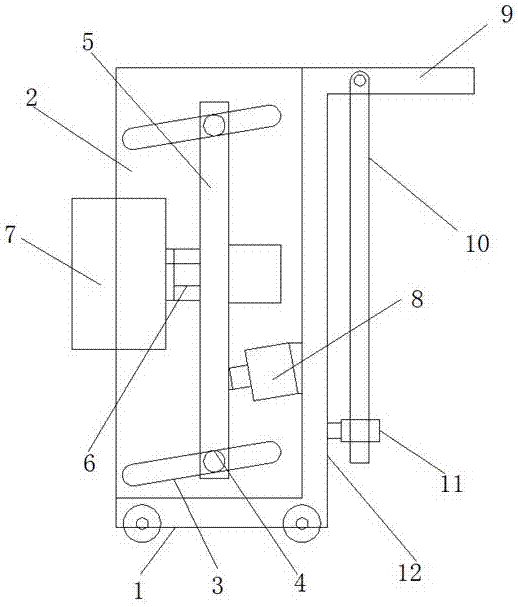
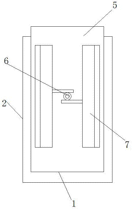
[0017] refer to Figure 1-2 , a lubricating oil barrel conveying device, comprising a base plate 1, a baffle plate 12 is vertically installed at one end of the base plate 1, side baffle plates 2 are vertically installed on both sides of the baffle plate 12, and side baffle plates 2 are symmetrically arranged along it. It is fixed and connected with the bottom plate 1. There are two sets of obliquely arranged waist holes 3 on the side of the side baffle 2 close to each other. The inside of the two sets of waist holes 3 is slidingly installed with the optical axis 4, and the outer side of the optical axis 4 is fixedly socketed. There is a movable plate 5, and a drive m...


PUM


Abstract

The invention discloses a lubricating oil barrel conveying device, which comprises a base plate, a baffle plate is vertically installed at one end of the base plate, side baffle plates arranged symmetrically along the baffle plate are vertically installed on both sides of the baffle plate, and the side baffle plate is fixed to the bottom plate There are two sets of oblique waist holes on the side of the side baffles that are close to each other. The optical axis is slidingly installed inside the two sets of waist holes, and the outer side of the optical axis is fixedly sleeved with a movable plate, which is far away from the baffle. A drive mechanism is installed on one side of the drive mechanism, and two groups of circular splints arranged symmetrically along the baffle are installed on the drive mechanism, and the splints are arranged in the vertical direction, and the side of the movable plate close to the baffle is installed with a fixed connection with the baffle. A push rod motor, a handle is vertically installed above the side of the baffle away from the movable plate, and a support rod is hinged on the side of the handle close to the bottom plate. The invention has quick operation direction, realizes the clamping operation of the lubricating oil drum, and facilitates the transportation of the lubricating oil drum.

Description

technical field [0001] The invention relates to the technical field of conveying devices, in particular to a lubricating oil drum conveying device. Background technique [0002] Lubricating oil is a liquid or semi-solid lubricant used in various types of automobiles and mechanical equipment to reduce friction and protect machinery and processed parts. It mainly plays the role of lubrication, auxiliary cooling, rust prevention, cleaning, sealing and buffering. Common Lubricating oil is mostly packed in barrels. Ordinary lubricating oil barrels are small in size and convenient for transportation and handling. However, lubricating oil for large machinery is packed in larger volume barrels, which is troublesome in transportation and handling. A lubricating oil barrel delivery device is needed for this purpose. . Contents of the invention [0003] The purpose of the present invention is to solve the shortcomings in the prior art, and propose a lubricating oil barrel conveying ...

Claims


Application Information

Patent Timeline
IPC IPC(8): B65G7/00
CPCB65G7/00
Inventor 周赤明周赤斌
Owner 阜宁县特种油品有限公司
Learn More