Workholding device for forging

A technology for workpiece clamping and forging, which is applied in the field of forging workpiece clamping devices, which can solve problems such as high cost, damage to forging machines, and easy damage, and achieve the effects of reasonable structure setting, fast clamping operation, and stable stability

Active Publication Date: 2020-12-04
山西有泉锻压股份有限公司
View PDF6 Cites 0 Cited by
  • Summary
  • Abstract
  • Description
  • Claims
  • Application Information

AI Technical Summary

Problems solved by technology

Among them, after the rough billet is heated at high temperature, the rough billet is forged with a forging machine. After the forging is completed, the product needs to be taken out from the forging machine. Generally, it is very inconvenient to use a special forklift device for clamping, and the high-temperature operation requires a particularly high labor intensity for the operator. The forklift is in a high-temperature state for a long time, and it is easy to be damaged, requiring frequent maintenance, and the cost is high.
At the same time, due to the different shapes of the forged products, especially the ring products, the forklift also needs very high operation skills when loading the products, and it is difficult to insert and remove, and it will damage the forging machine if you are not careful.
Therefore, the applicability and practicality are limited

Method used


Image

  • Workholding device for forging

Examples


Embodiment 1)

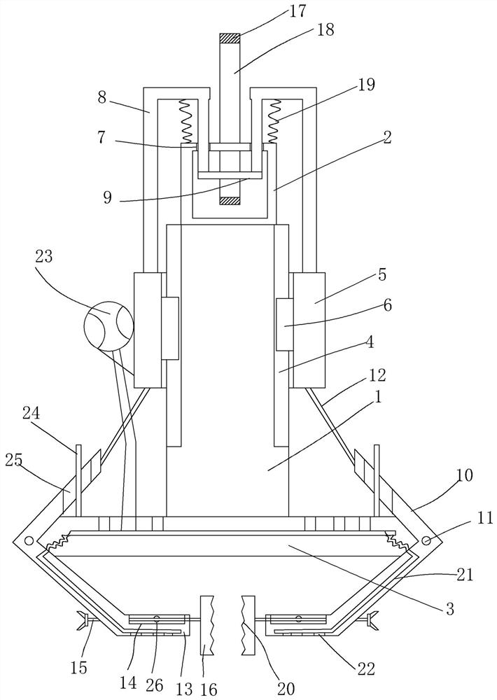
[0016] figure 1 A specific embodiment of the invention is shown in which figure 1 It is a structural schematic diagram of the present invention.

[0017] See figure 1 , a workpiece clamping device for forging, comprising a suspension rod 1, a suspension ring 2 fixed on the top end of the suspension rod and a clamping seat 3 fixed on the bottom end of the suspension rod, uniformly provided on the outer wall of the suspension rod The guide vertical groove 4 is provided with a collar 5 on the outside of the boom, and a guide slider 6 is integrally formed on the inner wall of the collar, and the guide slider is arranged in the guide vertical groove. The top wall of the suspension ring is provided with two circular holes 7, and an n-shaped support 8 is symmetrically fixed on the top of the collar, and the inner vertical rod of the n-shaped support extends into the suspension ring from the circular hole, and is arranged in the suspension ring. There is a transverse bearing bar 9,...


PUM


Abstract

The invention discloses a workpiece clamping device for forging. The workpiece clamping device comprises a lifting rod, a lifting ring fixed to the top end of the lifting rod, and a clamping seat fixed to the bottom end of the lifting rod; the outer wall of the lifting rod is uniformly provided with guide vertical grooves, and the outer side of the lifting rod is provided with a lantern ring; a guide sliding block is integrally formed on the inner wall of the lantern ring; the top wall of the lifting ring is provided with two round holes; n-shaped brackets are symmetrically fixed to the top end of the lantern ring; the lifting ring is internally provided with a transverse bearing rod; the clamping seat is provided with L-shaped clamping blocks, and transverse adjusting rods are integrallyformed at the lower ends of the L-shaped clamping blocks; and the top surfaces of the transverse adjusting rods are provided with adjusting sliding grooves, and adjusting screw rods penetrating through the adjusting sliding grooves are arranged on the transverse adjusting rods. The workpiece clamping device for forging is reasonable in structure arrangement, clamping operation of a forged workpiece can be effectively and quickly achieved, in addition, the positions of the adjusting screw rods are controlled according to different workpieces, the clamping stability can be ensured, the applicability is high, and the practicality is good.

Description

technical field [0001] The invention belongs to the technical field of forging equipment, and in particular relates to a workpiece clamping device for forging. Background technique [0002] Forging is a processing method that uses forging machinery to apply pressure to metal blanks to cause plastic deformation to obtain forgings with certain mechanical properties, certain shapes and sizes. It is one of the two major components of forging (forging and stamping). Among them, after the rough billet is heated at high temperature, the rough billet is forged with a forging machine. After the forging is completed, the product needs to be taken out from the forging machine. , Generally, it is very inconvenient to use a special forklift device for clamping, and the high-temperature operation requires a particularly high labor intensity for the operator. The forklift is in a high-temperature state for a long time, and it is easily damaged, requiring frequent maintenance, and the cost ...

Claims


Application Information

Patent Timeline
Patent Type & Authority Patents(China)
IPC IPC(8): B21J13/10
CPCB21J13/10
Inventor 叶晓丹
Owner 山西有泉锻压股份有限公司
Why Eureka
Try Eureka