Fan system and electric instrument

A fan system and electric motor technology, applied in the field of power transmission, can solve the problems of pressure relief, large backflow generated by the wind hood structure, and reduced conversion efficiency.

Inactive Publication Date: 2017-09-05
GUANGDONG WELLING ELECTRIC MACHINE MFG +1
View PDF11 Cites 7 Cited by
  • Summary
  • Abstract
  • Description
  • Claims
  • Application Information

AI Technical Summary

Problems solved by technology

[0002] The fan system is used to convert mechanical energy into gas pressure energy and kinetic energy. Usually, the fan system is a cavity with an inlet and an outlet composed of a fan cover and other components. The design of the fan cover structure w...

Method used


Image

  • Fan system and electric instrument
  • Fan system and electric instrument
  • Fan system and electric instrument

Examples


Embodiment Construction

[0028] In the present invention, unless stated otherwise, the used orientation words such as "upper and lower" usually refer to figure 1 In the directions shown in the drawings, "inside and outside" refer to figure 1 The interior and exterior of the various components of the blower system are shown.

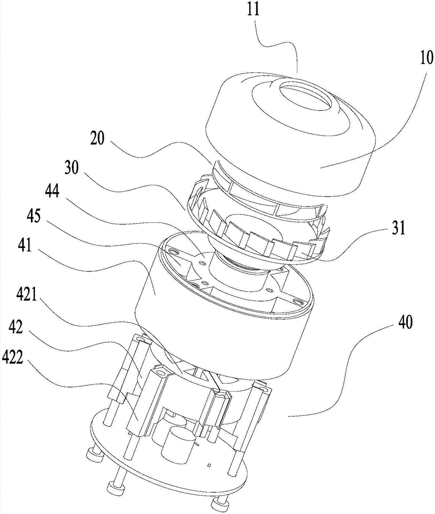
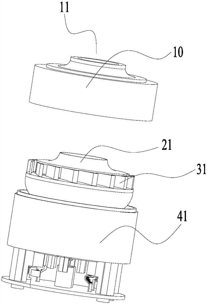
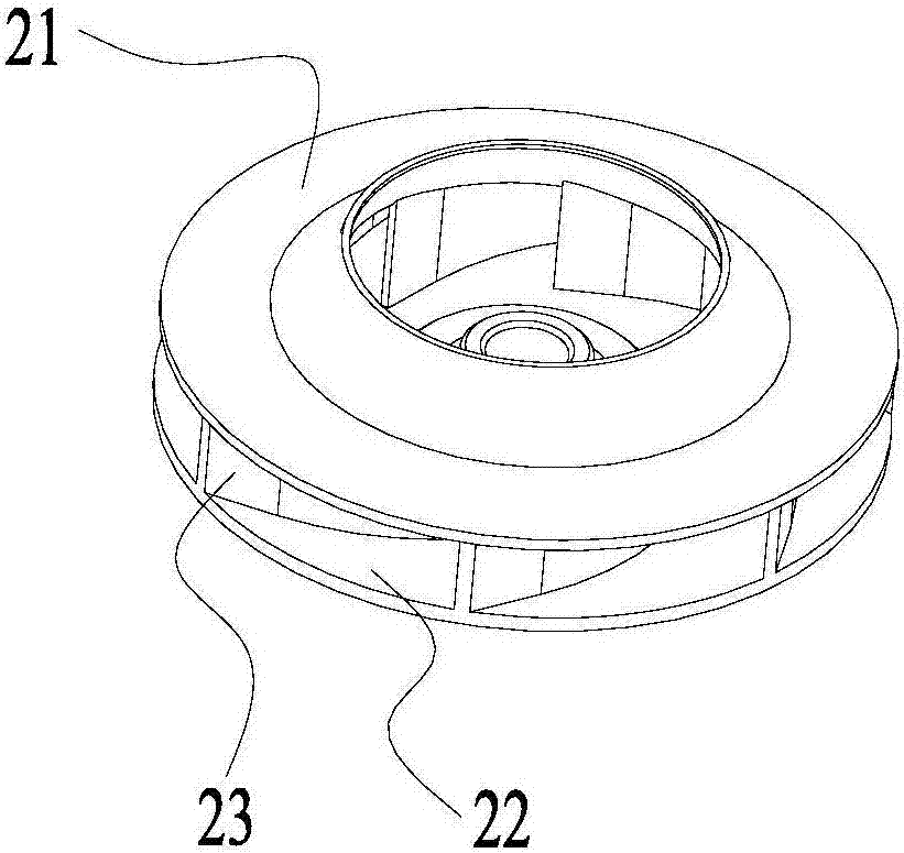
[0029] According to one aspect of the present invention, a fan system is provided, the fan system includes a wind cover 10 and a moving impeller 20, the wind cover 10 has an air inlet 11 and an annular groove 12 arranged around the air inlet 11, the The moving impeller 20 includes a front cover plate 21, the front cover plate 21 has a central through hole and is bent upward from the outside to the inside towards the central through hole, the top of the front cover plate 21 extends into the annular groove 12 and There is a gap with the side wall of the annular groove 12 .

[0030] Such as Figure 4 to Figure 6 As shown, since the wind shield 10 provided by the present invention...


PUM


Abstract

The invention relates to the technical field of power transmission and discloses a fan system and an electric instrument. The fan system comprises a fan cover (10) and a movable impeller (20). The fan cover (10) is provided with an air inlet (11) and a ring-shaped groove (12) formed around the air inlet (11). The movable impeller (20) comprises a front cover plate (21). The front cover plate (21) is provided with a center through hole and bent upwards toward the center through hole from outside to inside. The top of the front cover plate (21) extends into the ring-shaped groove (12), and a gap is kept between the top of the front cover plate (21) and the side wall of the ring-shaped groove (12). The fan system is utilized and can prevent backflow from being generated in the fan cover structure, and thus pressure relief is prevented to improve efficiency of the system.

Description

technical field [0001] The invention relates to the technical field of power transmission, in particular to a fan system and electric appliances. Background technique [0002] The fan system is used to convert mechanical energy into gas pressure energy and kinetic energy. Usually, the fan system is a cavity with an inlet and an outlet composed of a fan cover and other components. The design of the fan cover structure will directly affect the efficiency of the entire air duct system. , the structure of the windshield in the existing structure may generate a large backflow, causing a certain pressure relief, resulting in a large reduction in the conversion efficiency of the system. Contents of the invention [0003] The purpose of the present invention is to solve the problem of backflow in the fan system fan system structure in the prior art, and provide a fan system that can prevent the backflow generated by the fan system. [0004] In order to achieve the above object, t...

Claims


Application Information

Patent Timeline
IPC IPC(8): F04D29/44
CPCF04D29/444
Inventor 蒋婷婷冯国平刘俊龙刘亚琼陈金涛
Owner GUANGDONG WELLING ELECTRIC MACHINE MFG
Why Eureka
Try Eureka