Ultrasonic flowmeter

An ultrasonic flowmeter and ultrasonic technology, applied in the field of measurement, can solve the problems of difficult to use ultrasonic flowmeter, low measurement accuracy, application limitations, etc., and achieve the effects of simple control, avoidance of flow state changes, and flexible circuit processing.

Pending Publication Date: 2017-09-05
SHANGHAI YINUO INSTR
View PDF0 Cites 1 Cited by
  • Summary
  • Abstract
  • Description
  • Claims
  • Application Information

AI Technical Summary

Problems solved by technology

[0003] At present, ultrasonic flowmeters mainly measure low flow rates on the market, that is, ultrasonic flowmeters with a flow rate below 60m / s, which leads to excessive gas flow rates (usually above 100m / s) in the case of flare gas and high compressed gas pipelines. It is difficult to use an ultrasonic flowmeter; the traditional high-speed gas meter has disadvantages such as pressure loss and movable parts, which make the measurement accuracy low and its application is greatly limited

Method used


Image

  • Ultrasonic flowmeter
  • Ultrasonic flowmeter
  • Ultrasonic flowmeter

Examples


Embodiment Construction

[0024] The present invention will be further described in detail below in conjunction with the accompanying drawings and embodiments. It should be understood that the specific embodiments described here are only used to explain the present invention, but not to limit the present invention. In addition, it should be noted that, for the convenience of description, only some structures related to the present invention are shown in the drawings but not all structures.

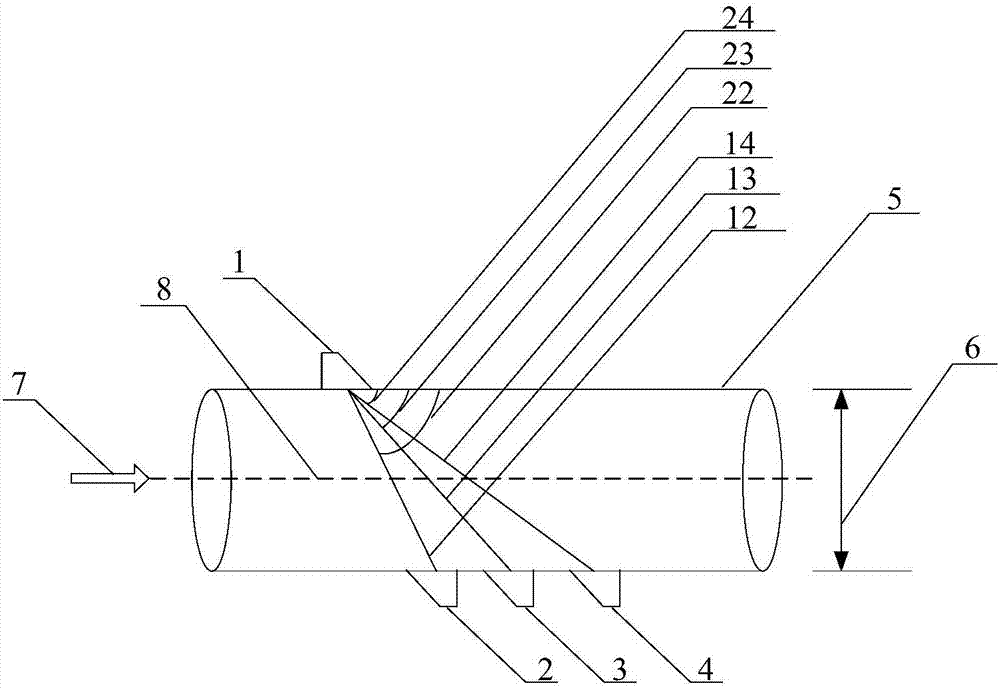
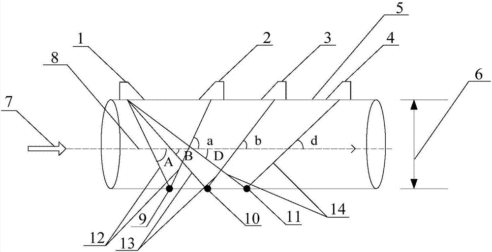
[0025] figure 1 An ultrasonic flowmeter provided for an embodiment of the present invention, such as figure 1 The ultrasonic flowmeter shown includes: a measuring tube 5; an ultrasonic transmitting transducer 1 positioned on the tube wall of the measuring tube 5 for transmitting ultrasonic signals; at least two ultrasonic receiving transducers positioned on the tube wall of the measuring tube 5 The transducer is used to receive the ultrasonic signal emitted by the ultrasonic transmitting transducer 1 . It should...


PUM


Abstract

The invention discloses an ultrasonic flowmeter, which comprises: a measuring tube; an ultrasonic transmitting transducer located on the tube wall of the measuring tube for transmitting ultrasonic signals; at least two transducers located on the tube wall of the measuring tube An ultrasonic receiving transducer is used to receive the ultrasonic signal transmitted by the ultrasonic transmitting transducer. In the present invention, the ultrasonic transmitting transducer is only used to transmit ultrasonic signals, and the ultrasonic receiving transducer is only used to receive the ultrasonic signals emitted by the ultrasonic transmitting transducer. For signal transmitting and receiving functions, the circuit processing of the ultrasonic flowmeter provided by the present invention is more flexible and the control is simpler. In addition, because the present invention arranges at least two ultrasonic receiving transducers to receive the ultrasonic signals emitted by the same ultrasonic transmitting transducer to calculate the flow velocity of the medium flowing through the measuring tube, it can largely avoid the problems caused by large time intervals. The change of the flow state makes the signal detection more accurate.

Description

technical field [0001] Embodiments of the present invention relate to measurement technology, and in particular to an ultrasonic flowmeter. Background technique [0002] Ultrasonic is widely used in gas and fluid flow rate measurement. Compared with traditional mechanical flowmeters and electromagnetic flowmeters, ultrasonic flowmeters have high measurement accuracy, strong adaptability to pipe diameters, non-contact fluids, and use Convenient, easy digital management and other advantages. [0003] At present, ultrasonic flowmeters mainly measure low flow rates on the market, that is, ultrasonic flowmeters with a flow rate below 60m / s, which leads to excessive gas flow rates (usually above 100m / s) in the case of flare gas and high compressed gas pipelines. It is difficult to use an ultrasonic flowmeter; the traditional high-speed gas meter has disadvantages such as pressure loss and movable parts, which make the measurement accuracy low and its application is greatly limite...

Claims


Application Information

Patent Timeline
Patent Type & Authority Applications(China)
IPC IPC(8): G01F1/66
CPCG01F1/662
Inventor 姜超李冰雨雷战胜王景帅
Owner SHANGHAI YINUO INSTR
Why Eureka
Try Eureka