Eureka AIR delivers breakthrough ideas for toughest innovation challenges, trusted by R&D personnel around the world.

A small construction simulation device for cutter suction dredger

The technology of a cutter suction dredger and a simulation device, which is applied in the field of small construction simulators of a cutter suction dredger, can solve the problems of high energy consumption, long time, and high test cost, and achieve good soil adaptability and land occupation The effect of small space and quick replacement

Inactive Publication Date: 2018-10-09
WUHAN UNIV OF TECH
View PDF4 Cites 0 Cited by
  • Summary
  • Abstract
  • Description
  • Claims
  • Application Information

AI Technical Summary

Problems solved by technology

[0002] For cutter suction dredgers, the construction parameters are closely related to the soil quality, and the optimization of construction parameters is closely related to the energy consumption and output of the dredger. In engineering practice, the selection and adjustment of dredging parameters often depend on the operator's on-site Based on experience, there is no experience and basis for the operation parameters of specific soil quality, and the use of professional large-scale construction simulation devices or the use of real ship tests is expensive, time-consuming, and energy-consuming
Moreover, in terms of scientific research, the observation of the movement law of underwater mud particles and the shape of the flow field is complicated, and computer simulation is often used, and its accuracy needs to be verified by experiments.

Method used


Image

  • A small construction simulation device for cutter suction dredger
  • A small construction simulation device for cutter suction dredger
  • A small construction simulation device for cutter suction dredger

Examples


Embodiment Construction

[0028] The present invention will be further described below with reference to the accompanying drawings and embodiments.

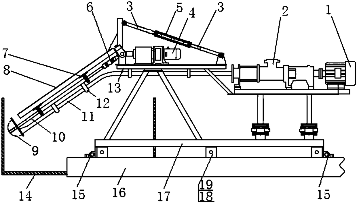
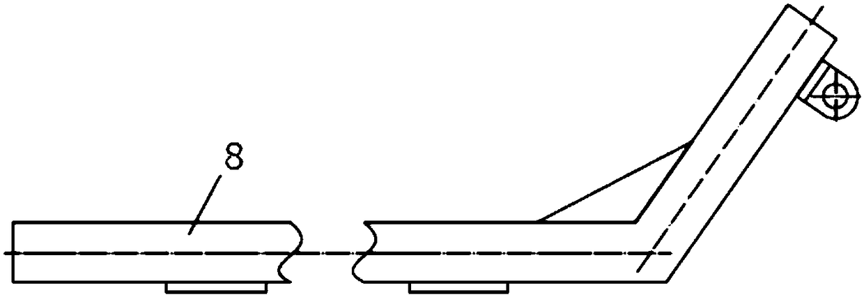
[0029] like figure 1 As shown, a small-scale construction simulation device for a cutter suction dredger includes electrical control equipment, a track 16 and a transparent and wear-resistant water tank 14. The track 16 is provided with a mobile frame 17, which is equipped with a Roller 18, the mobile motor 19 that provides power for the roller 18 (when the required torque is large, the mobile motor 19 is connected with the roller 18 through a reducer), the locking mechanism 15 that can fix the mobile frame 17, and the traverse motor 20 , the leading screw 22 that is connected with the traverse motor 20 and perpendicular to the track 16 (when the required torque is large, the traverse motor 20 is connected with the lead screw 22 through a reducer), the mud pump 2 and the mud pump 2 connected with the mud pump 2 The pump motor 1 and the lead screw 22 are ...


PUM


Abstract

The invention relates to a small construction simulating device for a cutter-suction type dredger. The small construction simulating device comprises electric control equipment, a rail and a transparent wear-resistant water tank. A movable rack is arranged on the rail, and the movable rack is provided with wheels, mobile motors, locking mechanisms, a transverse motor, a lead screw, a dredge pump and a dredge pump motor. The lead screw is matched with a sliding table which is provided with a rotary motor, a telescoping mechanism and a swing arm, and the rotary motor is connected with a transmission shaft through a universal joint. The transmission shaft is provided with a 3D print rimer which is located in the water tank, the telescoping end of the telescoping mechanism is hinged to the swing arm, a pressure sensor which is connected with the 3D print rimer is arranged on the portion, at an inlet of the dredge pump, of a mud conveying pipe, and a pressure sensor and a productivity meter are arranged on the portion, at an outlet of the dredge pump, of the mud conveying pipe. By means of the electric control equipment, construction operation can be simulated in a manual single-step mode and in a full-automatic mode. By means of the device, the functions of propulsion and positioning, transverse moving, swing lifting, rotational cutting and mud discharge of the cutter-suction type dredger can be simulated quickly at low cost, and underwater flow field observation is achieved.

Description

technical field [0001] The invention belongs to the field of cutter suction dredging, in particular to a small construction simulation device for a cutter suction dredger. Background technique [0002] For cutter suction dredgers, the construction parameters are closely related to the soil quality, and the optimization of construction parameters is closely related to the energy consumption and output of the dredger. In engineering practice, the selection and adjustment of dredging parameters often depend on the operator's on-site It is carried out empirically, and there is a lack of experience and basis for the operating parameters of specific soil properties, and the use of professional large-scale construction simulators or real ship tests is expensive, time-consuming, and energy-consuming. Moreover, in terms of scientific research, the movement rules of underwater mud particles and the observation of flow field morphology are complex, and computer simulation is often used...

Claims


Application Information

Patent Timeline
Patent Type & Authority Patents(China)
IPC IPC(8): G09B25/02
CPCG09B25/02
Inventor 范世东张敏张梦达朱汉华熊庭江攀黄豪飞
Owner WUHAN UNIV OF TECH
Why Eureka
Eureka Blog
Learn More