
RC oscillator

An oscillator and inverter technology, applied in the field of RC oscillator, to achieve the effect of eliminating deviation and good stability

Active Publication Date: 2017-09-05
IPGOAL MICROELECTRONICS (SICHUAN) CO LTD
View PDF6 Cites 5 Cited by
  • Summary
  • Abstract
  • Description
  • Claims
  • Application Information

AI Technical Summary

Problems solved by technology

However, polysilicon resistors vary by ±10% with temperature, voltage, and process angle, and MOS capacitors vary by more than ±10% with voltage, temperature, and process angle, and changes in delays introduced by inverters, buffers, etc. eventually lead to The frequency of the output clock CLK will deviate from the design frequency by ±20% deviation

Method used


Image

  • RC oscillator
  • RC oscillator
  • RC oscillator

Examples


Embodiment Construction

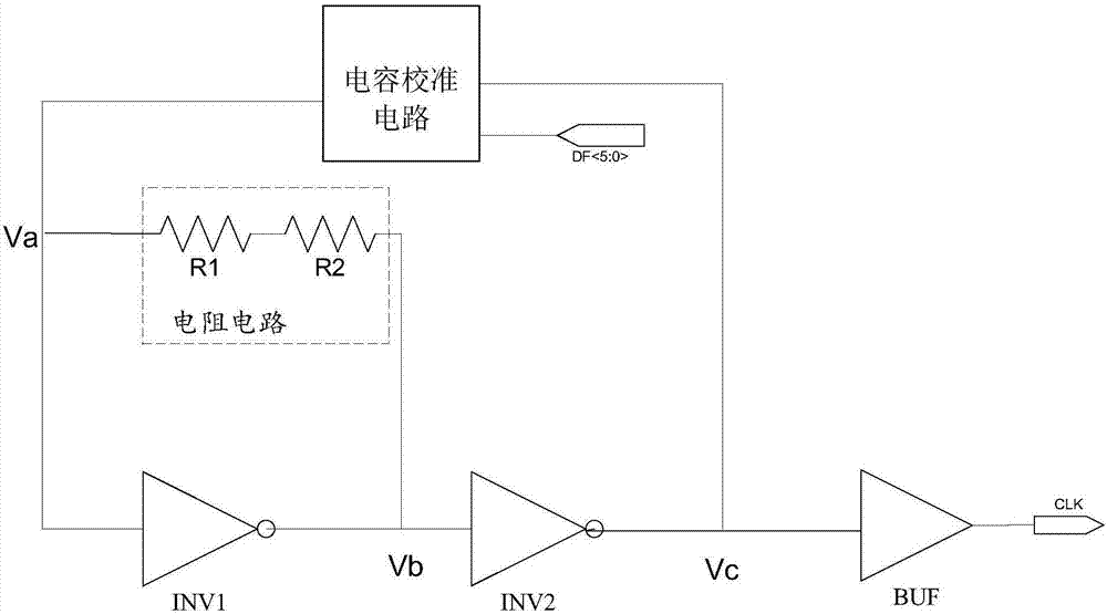
[0020] Embodiments of the present invention will now be described with reference to the drawings, in which like reference numerals represent like elements. As mentioned above, the present invention provides an RC oscillator. The capacitance value of the RC oscillator of the present invention is accurate, and does not change with temperature, voltage, and process; the resistance value does not change with temperature, and the deviation introduced by the MOS device is eliminated, and the output clock frequency Lock precisely around the design frequency.

[0021] Please refer to image 3 , image 3 It is a structural diagram of the RC oscillator of the present invention. The RC oscillator of the present invention includes a first inverter INV1, a second inverter INV2, a buffer BUF, a resistance circuit and a capacitance calibration circuit. The output terminal of the first inverter INV1 is connected to the input terminal of the second inverter INV2, the output terminal of the ...


PUM


Abstract

The invention discloses an RC oscillator, comprising a first phase inverter, a second phase inverter, a buffer and a resistor circuit. The output end of the first phase inverter is connected with the input end of the second phase inverter. The output end of the second phase inverter is connected with the input end of the buffer. The resistor circuit is connected between the input end and the output end of the first phase inverter. The RC oscillator also comprises a decoder, a basic capacitor and 2N-1 capacitor calibration units. Two ends of the basic capacitor are connected with the input end of the first phase inverter and the output end of the second phase inverter. Each capacitor calibration unit is connected with the input end of the first phase inverter and the output end of the second phase inverter. External N-bit binary control words are input into the control end of the decoder. Two output ends of the decoder output two groups of 2N-1-bit binary control words, and the two groups of 2N-1-bit binary control words are input into the capacitor calibration units. The RC oscillator is accurate in capacitance value, the capacitance value is not changed along with the temperature, a voltage and a technology, a resistance value is not changed along with the temperature, and an output clock frequency is precisely locked nearby a design frequency.

Description

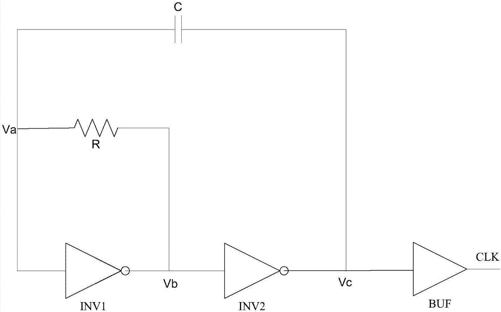
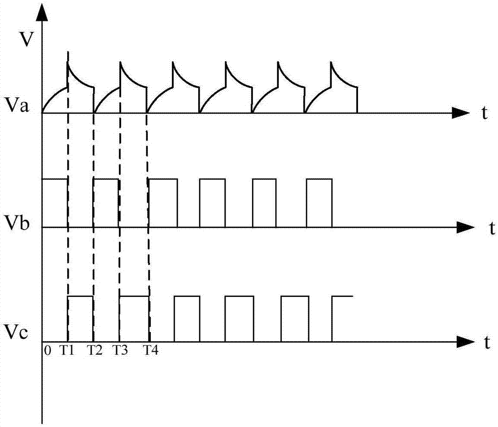
technical field [0001] The invention relates to the field of integrated circuits, in particular to an RC oscillator. Background technique [0002] Existing RC oscillator circuits such as figure 1 As shown, including two inverters INV1, INV2, buffer BUF, resistor R and capacitor C, the specific connection is as follows figure 1 shown. When the whole circuit starts running, that is, when the running time t is 0, it is assumed that the voltage of the node Va is 0, the voltage of the node Vb is 1, and the voltage of the node Vc is 0. During T1 time (that is, when 0<t<T1), the node Vb charges the capacitor C through the resistor R, and the voltage at the node Va rises; when t=T1, the voltage at the node Va reaches the reversal of the inverter INV1 voltage, the inverter INV1 flips; then, the voltage at the node Vb flips to 0, and the voltage at the node Vc flips to 1; when T1<t<T2, the node Va discharges the capacitor C through the resistor R, so that the voltage at...

Claims


Application Information

Patent Timeline
IPC IPC(8): H03B5/04H03B5/24
CPCH03B5/04H03B5/24
Inventor 陈景阔
Owner IPGOAL MICROELECTRONICS (SICHUAN) CO LTD
Learn More