
Recording apparatus and reading apparatus

A recording device and reading unit technology, which is applied in the directions of printing devices, printing, electrical components, etc., can solve the problems such as opening and closing without special consideration, and achieve the effect of realizing light weight, realizing miniaturization, and realizing cost reduction.

Active Publication Date: 2017-09-05
SEIKO EPSON CORP
View PDF3 Cites 0 Cited by
  • Summary
  • Abstract
  • Description
  • Claims
  • Application Information

AI Technical Summary

Problems solved by technology

[0009] In the above-mentioned image reading device of Patent Document 1 and the image forming device of Patent Document 2, no particular consideration is given to the opening and closing properties of the reading mechanism section relative to the recording mechanism section.

Method used


Image

  • Recording apparatus and reading apparatus
  • Recording apparatus and reading apparatus
  • Recording apparatus and reading apparatus

Examples


Embodiment 1

[0049] First, an outline of a recording device according to an embodiment of the present invention will be described. In this embodiment, an inkjet printer (hereinafter, simply referred to as a printer) is taken as an example of a recording device.

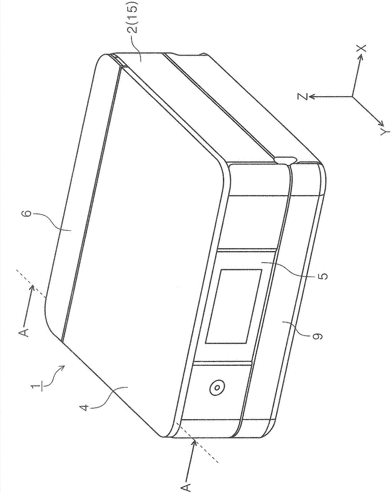
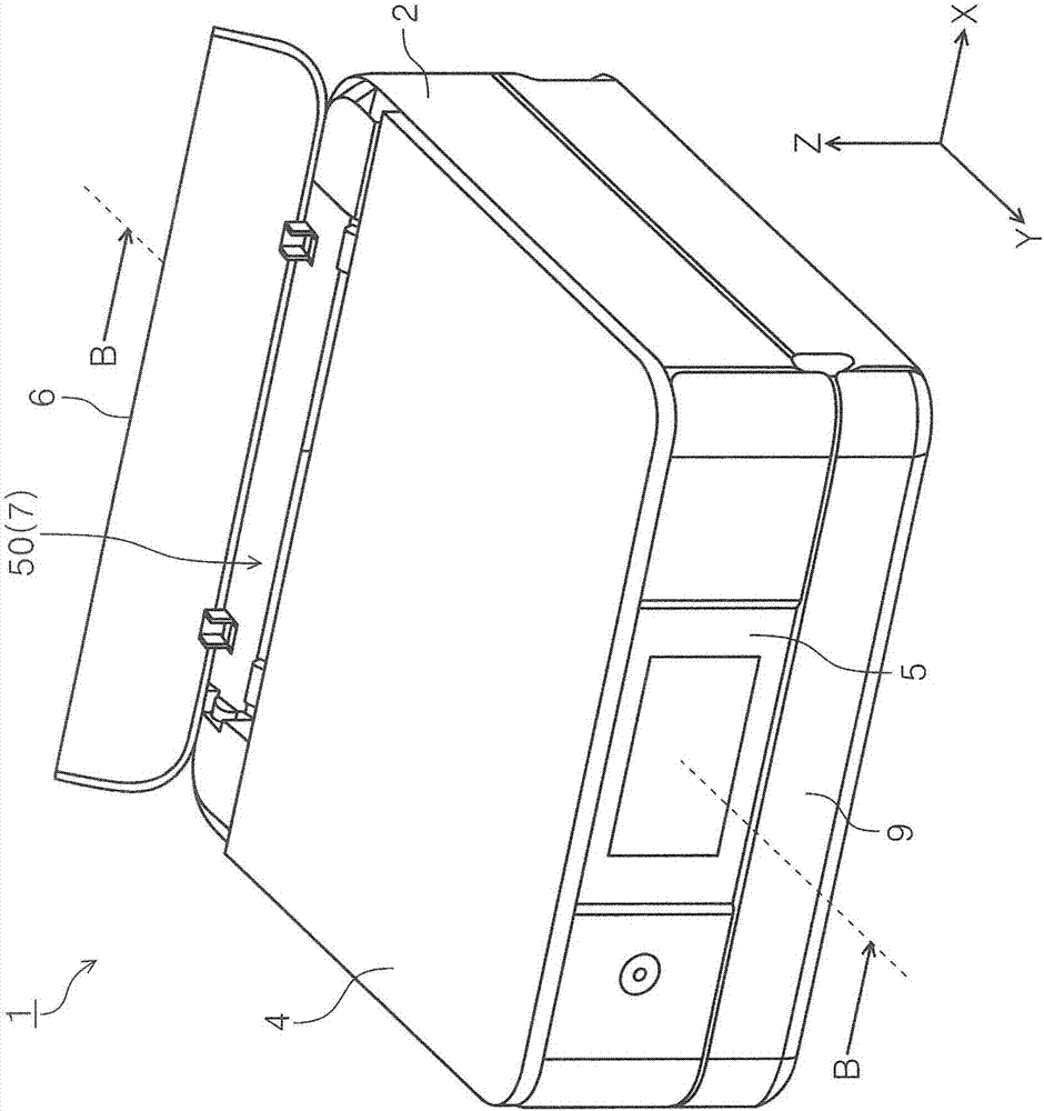
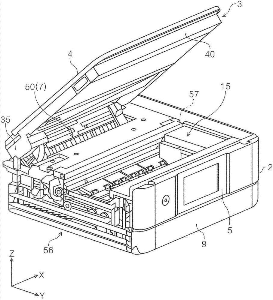
[0050] figure 1 It is a perspective view of the appearance of the printer of the present invention. figure 2 It is a perspective view showing a state in which the manual cover is opened in the printer of the present invention. image 3 It is a perspective view showing a state where the reading mechanism unit is closed in the printer of the present invention. Figure 4 is along figure 1 Cross-sectional view of the A-A arrow. Figure 5 is along figure 2 Cross-sectional view of the B-B arrow. Image 6 It is a perspective view of the reading mechanism unit. Figure 7 It is a plan view of the reading mechanism unit. Figure 8 It is a perspective view showing a state in which the document table is removed in the reading mechan...

Embodiment 2

[0126] Below, refer to Figure 17 , an example of the reading device of the present invention will be described. Figure 17 It is a perspective view showing a state where the document cover is opened in the reading device of the second embodiment.

[0127] Figure 17 The illustrated reading device 70 is configured with a reading mechanism section 71 having a reading unit 76 .

[0128] The reading unit 76 provided in the reading mechanism unit 71 and its moving mechanism 77 can have the same configuration as the reading unit 37 and moving mechanism 43 provided in the reading mechanism unit 3 of the printer 1 according to the first embodiment. Therefore, its detailed description is omitted.

[0129] In addition, in Figure 17 The illustration of the document table constituting the upper surface of the reading mechanism section 71 is omitted in the drawing.

[0130] Furthermore, the reading mechanism section 71 has Figure 17 The document cover 72 shown by the two dashed li...


PUM


Abstract

The invention provides a recording apparatus and a reading apparatus. The recording apparatus which is provided with a recording mechanism portion and a reading mechanism portion integratedly is provided with a moving mechanism of a reading unit of the reading mechanism portion with space saved, thus acheiving miniaturization of the recording apparatus. An apparatus main body including a recording mechanism portion that performs recording on a paper sheet; and a reading mechanism portion which is linked to the apparatus main body to be rotatable in an upper portion of the apparatus main body, and reads a document, the reading mechanism portion includes a reading unit which extends in a main scanning direction, and moves in an auxiliary scanning direction intersecting with the main scanning direction, a motor which moves the reading unit, and a first linking portion and a second linking portion which are disposed on the outside of a moving region when the moving region of the reading unit is viewed in a plan view, and are linked to the apparatus main body to be rotatable, and the motor is disposed at least in any of the first linking portion and the second linking portion.

Description

technical field [0001] The present invention relates to a recording device including a recording mechanism for recording on a recording medium and a reading mechanism for reading a document. Furthermore, it relates to a reading device for reading a document. Background technique [0002] Among the recording devices that record on a recording medium, there is a recording device that integrally includes a recording mechanism unit that records on a recording medium and a reading mechanism unit that reads a document. [0003] Furthermore, in the moving mechanism of the reading unit of the flat-head type reading mechanism (scanner), there is a mode in which the above-mentioned reading unit is fixed to a timing belt that is wound on a drive unit that is rotated by a drive source. The reading unit is pulled by rotating the driving pulley to move the timing belt and the driven pulley which rotates along with the driving pulley. [0004] In Patent Document 1, the timing belt is str...

Claims


Application Information

Patent Timeline
IPC IPC(8): H04N1/04H04N1/00B41J3/44
CPCB41J3/445H04N1/00535H04N1/00557H04N1/04B41J29/02B41J29/13B41J29/38H04N1/00543H04N1/00554H04N1/1026B41J2/01H04N2201/0094H04N2201/0446
Inventor 宫本真太郎冈泽善行
Owner SEIKO EPSON CORP
Learn More