
Metal powder split injection moulding and splicing and sintering method of hollow thin-walled structure

A thin-wall structure, metal powder technology, applied in the field of MIM process, can solve the problems of limited use of the same structure parts, unable to fully weld and seal, increase welding costs, etc., to reduce product costs, reduce costs, and improve sealing performance. Effect

Inactive Publication Date: 2018-07-27
杭州铭赫科技有限公司
View PDF5 Cites 0 Cited by
  • Summary
  • Abstract
  • Description
  • Claims
  • Application Information

AI Technical Summary

Problems solved by technology

[0005] In order to solve the problem that the existing injection molding splicing and sintering process increases the welding cost and cannot be completely welded and sealed, which makes the parts easy to rust in the incompletely sealed parts, and the parts cannot work in the state of immersion, which greatly limits many similar structures. The scope of use of the parts; at the same time, due to these design defects, the parts have great problems in terms of cost, structure, process, appearance, mechanical properties, etc., making the small household appliance industry that must be immersed in liquid seem to have no chance of the MIM process. The invention provides A hollow thin-walled structure metal powder separate injection molding splicing sintering method is designed, and a process of separate injection, assembly and sintering is designed. This process does not require subsequent auxiliary processes such as welding. After sintering, it is a finished product, and the sealing of the parts is perfect. After the parts are hollowed out, only one layer of thin wall is left, which is very light in weight

Method used


Image

  • Metal powder split injection moulding and splicing and sintering method of hollow thin-walled structure
  • Metal powder split injection moulding and splicing and sintering method of hollow thin-walled structure
  • Metal powder split injection moulding and splicing and sintering method of hollow thin-walled structure

Examples


Embodiment

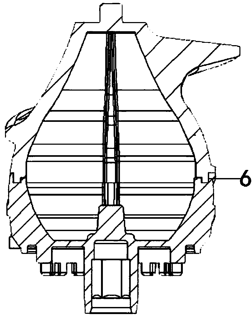
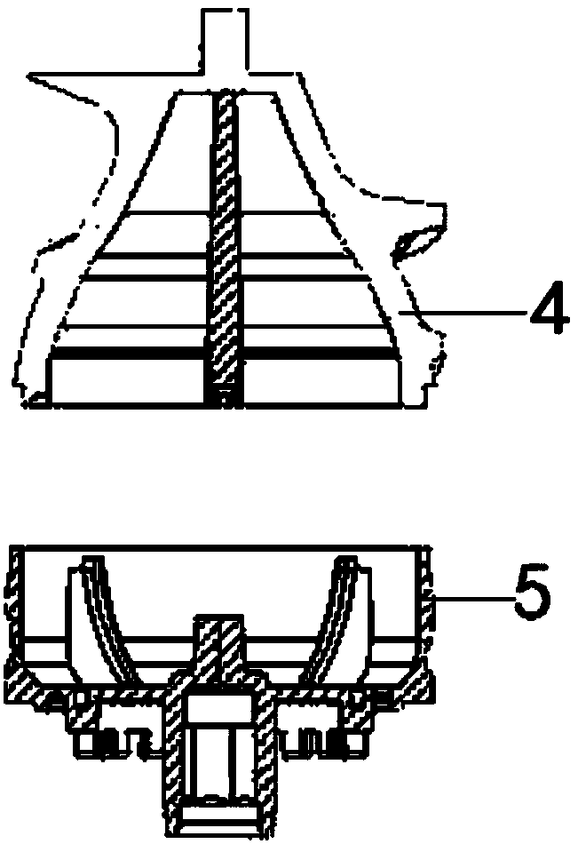
[0022] Such as Figure 1-3 Shown: the present invention provides a hollow thin-wall complex structure metal powder separate injection molding splicing sintering method, the hollow thin-wall structure is split and designed into an upper shell injection part and a lower shell injection part, and the internal structure is hollowed out , injecting the upper shell injection part and the lower shell injection part separately;

[0023] Assemble the plate according to the original fool-proof structure of the injection part of the upper shell and the injection part of the lower shell. After assembling the injection part of the upper shell and the injection part of the lower shell, degrease and sinter; cut according to the outer structure of the product, The two joining surfaces of the injection part of the upper shell and the injection part of the lower shell are matched on the same arc line.

[0024] Figure 4 to Figure 5 For the traditional injection sintering method, separate inje...


PUM


Abstract

The invention provides a metal powder split injection moulding and splicing and sintering method of a hollow thin-walled structure. A technology of split injection and assembled sintering is designed,and does not require subsequent auxiliary processes such as welding, a finished product is obtained after sintering, the sealability of a part is very perfect, and after the interior of the part is hollowed out, simply a layer of an outer thin wall is left, so that the part is very low in weight. The method comprises the following steps that the hollow thin-walled structure is split and designedinto an upper housing injection piece and a lower housing injection piece, an inner structure is hollowed out, and the upper housing injection piece and the lower housing injection piece are split, and injected separately; and assembling and arranging are conducted according to a predetermined fool-proof structure of the upper housing injection piece and the lower housing injection piece, and theupper housing injection piece and the lower housing injection piece are assembled and then are degreased and sintered.

Description

technical field [0001] The invention relates to a MIM process flow, in particular to a hollow thin-wall complex structure metal powder separate injection molding splicing and sintering process method. Background technique [0002] For the existing production of most large parts with complex shapes, because it is impossible to escape from the inside of the part, it is mainly completed by solid body injection molding. Solid body injection molding not only increases the cost of the product, but also makes it difficult to The requirements for production equipment are also very high, so the process form does not meet the needs of corporate profits; secondly, the wear resistance of plastic parts is not good, and the service life cannot meet the needs of end customers. The industry expects to use metal parts to replace plastic parts. Very high; the previous MIM process is: separate injection molding---separate degreasing---separate sintering---assembly welding---polishing and joini...

Claims


Application Information

Patent Timeline
Patent Type & Authority Applications(China)
IPC IPC(8): B22F3/115B22F3/10B22F5/10
CPCB22F3/115B22F3/10B22F3/1021B22F5/10
Inventor 胡波林
Owner 杭州铭赫科技有限公司
Learn More