A method of manufacturing an airbag-assisted composite material reinforced wall panel

A technology of reinforced wall panels and composite materials, which is applied to household appliances, other household appliances, household components, etc., can solve problems such as uneven pressure on ribs, internal quality problems of parts, and axis deviation of surface quality, so as to prevent Resin loss, guaranteed thickness, high precision effect

Active Publication Date: 2019-11-15
SHENYANG AIRCRAFT CORP
View PDF4 Cites 0 Cited by
  • Summary
  • Abstract
  • Description
  • Claims
  • Application Information

AI Technical Summary

Problems solved by technology

If the form of a double-sided metal mandrel is used, the shape of the ribs can be well guaranteed, but this form involves the cooperation between tooling and often requires extremely high machining accuracy, which puts extremely high demands on the manufacture of the metal mandrel. requirements
In addition, the continuous stress of the metal tooling during repeated use may cause slight deformation of the local profile. The pressure transmission through such metal tooling will cause uneven pressure on the ribs, which may lead to internal quality problems of the parts
If the form of double-sided airbags is used, it can ensure the uniform transmission of pressure, and then ensure the quality of curing, but the double-sided airbags are made of soft materials, which cannot guarantee the shape of the ribs, which may cause surface quality problems and axis trend deviation
If one-sided solid rubber soft mold is used in combination with one-sided metal mandrel, the shape of the ribs can be guaranteed in the same way, but the pressure during the curing process comes from the expansion of the rubber soft mold itself, and the value and transmission process of this part of the pressure cannot be explained. Uniformity in

Method used


Image

  • A method of manufacturing an airbag-assisted composite material reinforced wall panel
  • A method of manufacturing an airbag-assisted composite material reinforced wall panel
  • A method of manufacturing an airbag-assisted composite material reinforced wall panel

Examples


Embodiment

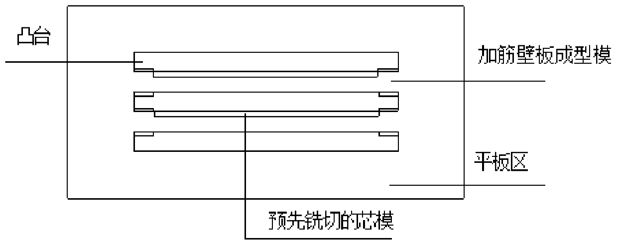
[0017] As shown in Figure 1, taking the forming of T-shaped ribs as an example, the main form of the reinforced wall panel forming mold is a convex flat plate forming die, and the bottom of the flat plate is a frame structure. The area is used for vacuum bag packaging, so the size of the boss is slightly larger than the size of the skin, and the size of the flat plate is slightly larger than the size of the boss. On the forming boss, groove is made according to the position and shape of the rib. The width of the groove is slightly larger than the width of the lying side of the rib, and the depth is slightly smaller than the height of the rib. The length is the through groove that runs through the entire boss. The two ends are provided with a cover plate that can cover the groove, and one side of the groove is directly milled out according to the length of the rib to form a rib forming mandrel integrated with the rib forming mold.

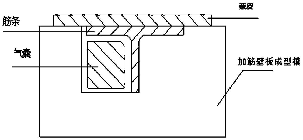
[0018] Such as figure 2 As shown, the airba...


PUM


Abstract

The invention belongs to the technical field of composite material processing molding and provides an airbag-assisted production method for a composite material stiffened wall plate. Through a co-curing method, rods can be in a T shape, or a J shape or an L shape. A molding tool comprises a forming die, an airbag molding die and a rib laying die. The method has the following advantages that (1) extrusion molding of ribs are achieved through a metal core die and a rubber airbag, the metal core die can ensure the outline of the ribs, the pressure in the a heat pressure tank can be effectively transmitted to parts through the airbag, pressure can be applied to the parts uniformly, and the curing quality of the ribs is ensured; (2) groove positions of the forming die are completed through numerical-control milling, the precision is high, and the axial lines of the ribs can be ensured in the whole curing period; and (3) the ribs are integrally formed in the grooves , the loss of resin can be prevented through the metal core die on one side, a whole die cavity can be filled through the airbag on the other side in the inflated state, the loss of the resin can be prevented and the thickness of the parts can be ensured.

Description

technical field [0001] The invention belongs to the technical field of composite material processing and molding, and relates to a method for manufacturing an airbag-assisted composite material reinforced wallboard. Background technique [0002] With the extensive application of composite materials in military and civilian aircraft, some key and important parts are designed in the form of reinforced panels. Combining ribs on the skin can basically guarantee the quality of the skin, but for the ribs, it is necessary to control the accuracy of the shape of the ribs, such as flatness and axis direction, and ensure the quality of curing. At present, the forming tooling of ribs is mainly in the form of double-sided metal mandrel, double-sided airbag or single-sided solid rubber soft mold combined with unilateral metal mandrel. If the form of a double-sided metal mandrel is used, the shape of the ribs can be well guaranteed, but this form involves the cooperation between tooling ...

Claims


Application Information

Patent Timeline
Patent Type & Authority Patents(China)
IPC IPC(8): B29D99/00
CPCB29D99/0014
Inventor 叶真铭李景钰姜洪博张晓哲
Owner SHENYANG AIRCRAFT CORP
Why Eureka
Try Eureka