
Road safety protection device

A safety protection device, road technology, applied in the direction of road safety devices, roads, roads, etc., can solve the problems of high manufacturing and maintenance costs, affecting vehicle safety, overturning, etc., to achieve easy disassembly and installation, easy installation, and guaranteed service life Effect

Inactive Publication Date: 2017-09-08
刘斌
View PDF6 Cites 7 Cited by
  • Summary
  • Abstract
  • Description
  • Claims
  • Application Information

AI Technical Summary

Problems solved by technology

[0002] The road guardrail is a commonly used isolation protection device. Since pedestrians need to step over the guardrail to the outer safety area of ​​the road in case of an accident and avoid driving on the road, the height of the guardrail should not be too high. When the height of the guardrail is low, When a vehicle loses control and hits the guardrail, when the impact is severe, the vehicle may turn over at the guardrail, causing more serious injuries, or affecting the safety of vehicles on other roads, so the guardrail should be lower for convenience Pedestrians step over to the safe area, there should also be a higher height to reduce the flipping at the guardrail when the vehicle hits
And the road guardrail protection device should be simple and effective in structure, and the complex device structure brings higher manufacturing and maintenance costs

Method used


Image

  • Road safety protection device
  • Road safety protection device
  • Road safety protection device

Examples


Embodiment Construction

[0023] The present invention will be further described in detail below in conjunction with the accompanying drawings and specific embodiments.

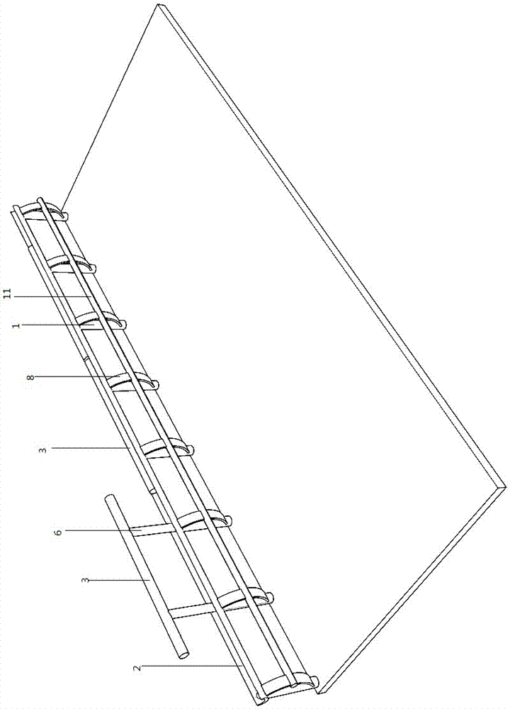
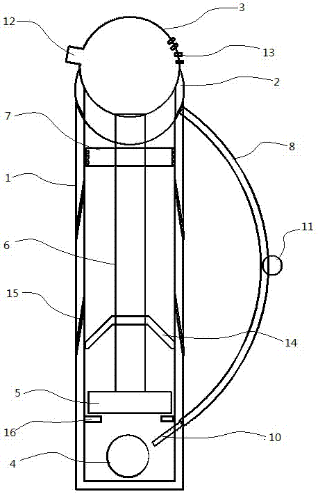
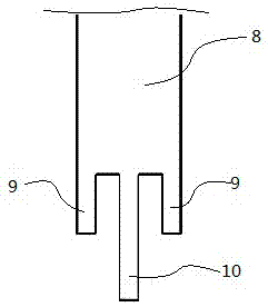
[0024] Such as Figure 1-4 As shown, the road safety protection device includes fixed pipes 1 evenly distributed along the road, and a horizontal crescent-shaped trusteeship 2 fixedly connected to the upper end of the fixed pipe 1; the lower end of the fixed pipe 1 is fixedly connected to the road surface, and the upper end of the fixed pipe 1 is open and connected 2 are connected; a plurality of connecting pipes 3 are uniformly distributed in the hosting 2; explosive packs 4 are installed at the bottom of the fixed pipe 1; a piston 5 is slidingly connected in the fixed pipe 1; a push rod 6 is vertically fixedly connected to the upper end of the piston 5; 6 The top is fixedly connected to the side of the connecting pipe 3 corresponding to the top; the upper part of the fixed pipe 1 is connected to the limit device 7; ;Such as image...


PUM


Abstract

The invention discloses a road safety protection device, and relates to the technical field of road fences. The road safety protection device comprises fixing pipes evenly distributed along a road. A plurality of connecting pipes are evenly distributed in supporting pipes in a matched mode. An explosive bag is installed at the bottom in each fixed pipe. A piston is connected into each fixed pipe in a sliding mode. The upper end of each piston is perpendicularly and fixedly connected with a push rod. The top end of each push rod is fixedly connected with the lateral side of the upper corresponding connecting pipe. A limiting device is connected with the upper portion in each fixed pipe. The lateral side of each fixed pipe is connected with an arc-shaped buffering plate. The upper end of each buffering plate is fixedly connected with the upper portion of each fixed pipe. The lower end of each buffering plate is shaped like an inverted Chinese character 'shan', wherein buffering supporting plates are arranged on the two sides, and a detonating plate is arranged in the middle. A through hole matched with the corresponding detonating plate is formed in the side wall of each fixed pipe. Each detonating plate penetrates through the corresponding through hole to be opposite to the corresponding explosive bag. The buffering supporting plates make contact with the lateral sides of the fixed pipes. The middles of all the buffering plates are connected through a connecting rod. The road safety protection device has the advantages of being simple in structure, rapid in response, safe and effective and capable of rapidly rising to stop a vehicle and prevent overturn.

Description

technical field [0001] The invention relates to the technical field of road guardrails. Background technique [0002] The road guardrail is a commonly used isolation protection device. Since pedestrians need to step over the guardrail to the outer safety area of ​​the road in case of an accident and avoid driving on the road, the height of the guardrail should not be too high. When the height of the guardrail is low, When a vehicle loses control and hits the guardrail, when the impact is severe, the vehicle may turn over at the guardrail, causing more serious injuries, or affecting the safety of vehicles on other roads, so the guardrail should be lower for convenience When pedestrians cross to the safe area, there should also be a higher height to reduce the overturning at the guardrail when the vehicle hits. Moreover, the road guardrail protection device should have a simple and effective structure, and the complex device structure brings about higher manufacturing and mai...

Claims


Application Information

Patent Timeline
IPC IPC(8): E01F15/02E01F15/14
CPCE01F15/02E01F15/14E01F15/145
Inventor 不公告发明人
Owner 刘斌
Learn More