Coil winding paying-off device

A pay-off device and coil technology, applied in coil manufacturing, transportation and packaging, inductance/transformer/magnet manufacturing, etc. The effect of convenient crossing, simple operation and controllable wire tension

Active Publication Date: 2015-07-15
ALLTECH MEDICAL SYST
View PDF8 Cites 12 Cited by
  • Summary
  • Abstract
  • Description
  • Claims
  • Application Information

AI Technical Summary

Problems solved by technology

[0003] The existing winding equipment is generally designed according to the winding of a single wire, and there is only a single pay-off frame. On the rack, pull the two wires onto the winding machine skeleton, adjust the length of the two wires to make them almost one and fixed, turn on the winding tension to start winding, because this type of winding machine only has one tension output pay-off rack, and the two wires The distance from the bobbin to the coil bobbin cannot be guaranteed to be one to one. With the unwinding of the two wires, the distance will become larger and larger, so there will always be no tension or small tension on one wire, which will affect the winding quality.
In addition, when each layer of wires is wound and the lower layer of wires is wound, the left and right positions of the two wires need to be crossed and reversed, so that the length of the two wires becomes more different after the crossover, which affects the coil winding quality.

Method used


Image

  • Coil winding paying-off device
  • Coil winding paying-off device
  • Coil winding paying-off device

Examples


Embodiment Construction

[0021] In order to make the object, technical solution and advantages of the present invention clearer, the present invention will be further described in detail below in conjunction with the accompanying drawings.

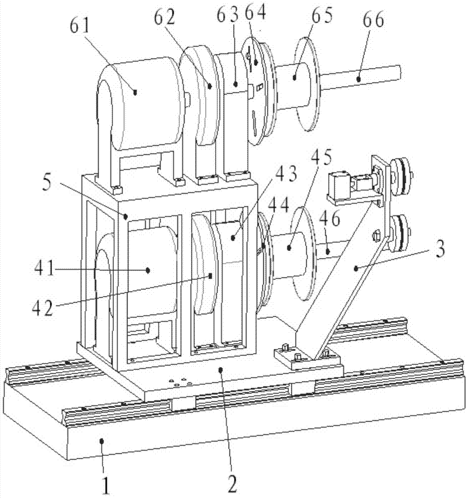
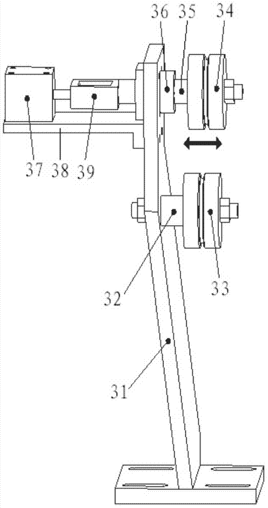
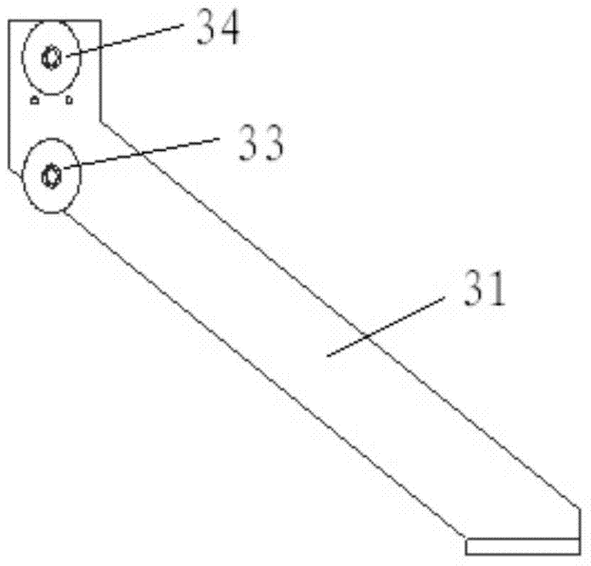
[0022] like figure 1 As shown in -3, the coil winding pay-off device of the present invention includes a workbench 2, an upper tension pay-off mechanism 6, a lower tension pay-off mechanism 4, a frame 5, and a wire crossing reversing mechanism 3; the upper tension pay-off mechanism The mechanism 6 is installed on the frame 5, and the frame 5 is installed on the workbench 2; the lower tension pay-off mechanism 4 is installed on the workbench 2 and is located below the upper tension pay-off mechanism 6; the wire crossing reversing mechanism 3 is installed on the workbench 2.

[0023] Further, the upper tension pay-off mechanism 6 includes an upper motor 61, an upper clutch 62, an upper shaft 66, and an upper pay-off reel 65; the upper shaft 66 is connected to the o...


PUM


Abstract

A coil winding paying-off device comprises a workbench, an upper tension paying-off mechanism, a lower tension paying-off mechanism, a rack and a wire crossing and reversing mechanism. The upper tension paying-off mechanism is installed on the rack which is installed on the workbench, the lower tension paying-off mechanism is installed on the workbench and located below the upper tension paying-off mechanism, the wire crossing and reversing mechanism is installed on the workbench, and the workbench is installed on a horizontal moving sliding table. According to the coil winding paying-off device, the upper tension paying-off mechanism and the lower tension paying-off mechanism provide independent tension output for two sets of paying-off coils respectively, the wire crossing and reversing mechanism conducts left and right crossing and reversing on wires of each layer in the coil winding process, and the horizontal moving sliding table adjusts the double tension paying-off mechanisms and the wire crossing and reversing mechanism to move left and right in the coil winding process; by means of the coil winding paying-off device, the tension of all the wires in the coil winding process is more controllable, crossing of the wires among the layers is more convenient, and the operation is easier.

Description

technical field [0001] The present invention relates to a coil-winding wire pay-off device, in particular to a wire pay-off device in which the tension of the double-strand wires is controlled separately and the wires can be crossed left and right to rewind the coil. Winding. Background technique [0002] The commonly used non-inductive coil winding method is the double winding method, which is to fold a piece of wire from the midpoint and put them together. Then the two wires are cross-wound left and right. Left and right cross winding means that when the two parallel wires are on the current layer, one is outside the winding direction. After changing to the next layer, the two wires need to be crossed left and right so that this wire is still outside the winding direction. Wind in this way until the last two wires go out. [0003] The existing winding equipment is generally designed according to the winding of a single wire, and there is only a single pay-off frame. On...

Claims


Application Information

Patent Timeline
Patent Type & Authority Applications(China)
IPC IPC(8): H01F41/06B65H59/04B65H57/14H01F41/094H01F41/096
Inventor 朱红波卞文龙张涛
Owner ALLTECH MEDICAL SYST
Why Eureka
Try Eureka