Cylindrical cuspend magnetic field thruster

A tangential magnetic field and cylindrical technology, which is applied in the field of cylindrical tangential magnetic field thrusters, can solve the problems of long ceramic channel length and small radial size of the thruster, and achieve the reduction of axial size and increase of radial size , The effect of improving the utilization rate

Inactive Publication Date: 2015-05-06
HARBIN INST OF TECH
View PDF8 Cites 12 Cited by
  • Summary
  • Abstract
  • Description
  • Claims
  • Application Information

AI Technical Summary

Problems solved by technology

[0003] The purpose of the present invention is to solve the problem that the radial size of the existing ionization zone is very small, resulting in a very long length of the thruster ceramic channel, and then provide a cylindrical tangential magnetic field thruster

Method used


Image

  • Cylindrical cuspend magnetic field thruster
  • Cylindrical cuspend magnetic field thruster
  • Cylindrical cuspend magnetic field thruster

Examples


specific Embodiment approach 1

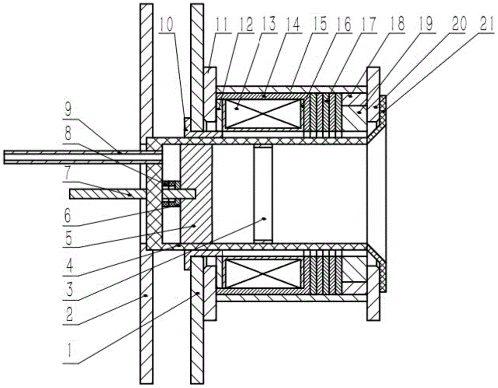
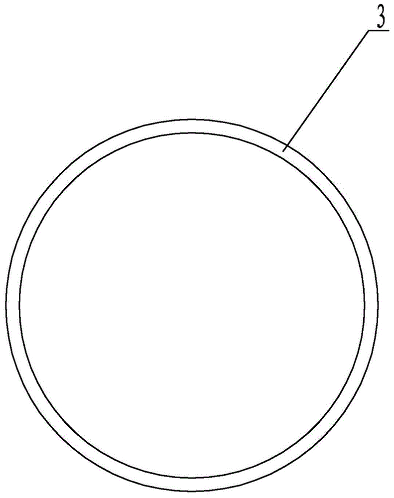
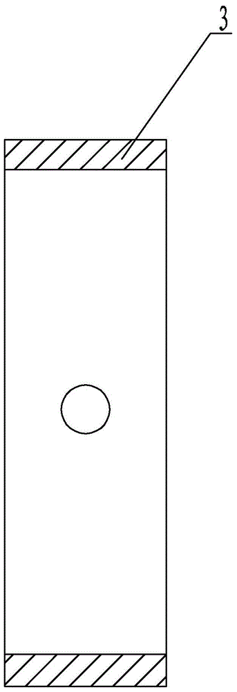
[0010] Specific implementation mode one: combine figure 1 , figure 2 with image 3 Describe this embodiment, a cylindrical tangent magnetic field thruster of this embodiment includes a bracket plate 1, a ceramic base 2, an annular anode 3, a cylindrical ceramic channel body 4, a gas distributor 5, a nut 6, and a conductive bolt 7 , two ceramic gaskets 8, air guide 9, aluminum alloy bracket 10, first aluminum alloy bracket 11, magnetic guide base 12, coil 13, first magnetic guide 14, outer aluminum alloy sleeve 15, coil support 16. Ceramic end cap 21, magnet bracket 18, magnet 19, second aluminum alloy end cap 20, ceramic end cap 21 and a plurality of second magnetically conductive parts 17,

[0011] The left end of the cylindrical ceramic channel body 4 is processed with two working fluid jet holes, the air guide 9 is installed on one of the working fluid jet holes, the conductive bolt 7 is penetrated on the other working fluid jet hole, and the two ceramic gaskets 8 are s...

specific Embodiment approach 2

[0014] Specific implementation mode two: combination figure 1 To illustrate this embodiment, the annular anode 3 in the middle of the inner wall of the cylindrical ceramic channel body 4 is located in the middle of the coil 13 on the outer wall of the cylindrical ceramic channel body 4 in this embodiment. Such setting will change the potential distribution inside the ceramic channel body 4, so that electrons have a tendency to move toward the side wall of the channel. During the movement of electrons to the anode on the side wall of the channel, they need to cross multiple magnetic induction lines in the radial direction, so more electrons will be distributed in the area away from the central axis of the channel, thereby increasing the radial size of the ionization zone and making it Increased channel utilization. Other compositions and connections are the same as in the first embodiment.

specific Embodiment approach 3

[0015] Specific implementation mode three: combination figure 1 Describe this embodiment, the annular anode 3 of this embodiment is fixed on the outer wall of the cylindrical ceramic channel body 4 by bolts, and the wire passes through the bolts fixed on the outer wall of the cylindrical ceramic channel body 4 and the annular anode 3 connect. With such an arrangement, on the one hand, the position of the ring-shaped anode 3 can be changed relatively easily, and on the other hand, the drawn-out wires will not interfere with the movement of electrons inside the channel. Other compositions and connections are the same as those in Embodiment 1 or Embodiment 2.


PUM


Abstract

The invention relates to a cylindrical cuspend magnetic field thruster, and relates to a cuspend magnetic field thruster, which aims at solving the problem of overlong thruster ceramic passage caused by the smaller radial size of the existing ionizing area. An air guide device is arranged on a working medium spraying hole, a conducting bolt is arranged in the other working medium spraying hole in a penetrating way, two ceramic gaskets sleeve the conductive bolt and are fixed by a nut, an annular anode is fixedly arranged in the middle part of the inside wall of a cylindrical ceramic channel body, an air distributor is arranged in the cylindrical ceramic channel body, a second aluminum alloy end cover, a magnet, a plurality of second magnetic pieces, a first magnetic piece, a coil, a magnetic piece base, a first aluminum alloy bracket and a bracket plate sequentially sleeve the outside wall of the cylindrical ceramic channel body from right to left, the magnet bracket sleeves the magnet, the coil bracket sleeves the coil, the outer aluminum alloy sleeve sleeves the first magnetic piece, the second magnetic pieces and the magnet bracket, and the aluminum alloy bracket sleeves the outer wall of the cylindrical ceramic channel body. The cylindrical cuspend magnetic field thruster is applied to the field of aerospace.

Description

technical field [0001] The invention relates to a cusp magnetic field thruster, in particular to a cylindrical cusp magnetic field thruster. Background technique [0002] The tangent magnetic field plasma thruster is a new type of electric propulsion device based on the Hall thruster. The wall surface of the discharge channel of the thruster is generally composed of ceramics, surrounded by multi-stage permanent magnets, and the two adjacent permanent magnets have opposite polarities. An anode is arranged upstream of the channel. The working gas is sprayed into the discharge channel through the gas supply pipeline. Outside the exit of the thruster, a hollow cathode is placed, which can emit electrons. Due to the high magnetic field strength inside the channel, the Lorentz force on the electrons is very large, and the radius of gyration is small, so the electrons mainly move helically along the magnetic field lines, and the electrons only have the opportunity to cross the m...

Claims


Application Information

Patent Timeline
Patent Type & Authority Applications(China)
IPC IPC(8): F03H1/00
CPCF03H1/00
Inventor 刘辉伍环张俊友杨思雨孟颖超胡鹏高圆圆
Owner HARBIN INST OF TECH
Why Eureka
Try Eureka