Raw material air drying device adopted after silk screening and used for manufacturing of ceiling lamp lampshade

A technology for ceiling lamp shades and raw materials, applied in lighting and heating equipment, dryers for static materials, drying, etc., can solve problems such as slow drying speed, and achieve good air-drying effects

Inactive Publication Date: 2017-09-08
GRACE(NINGBO) LIGHTING CO LTD
View PDF0 Cites 7 Cited by
  • Summary
  • Abstract
  • Description
  • Claims
  • Application Information

AI Technical Summary

Problems solved by technology

[0003] To sum up, at present, it is necessary to develop an air-drying equipment for raw materials for ceiling lamp shades that can be quickly air-dried and the air-drying speed can be adjusted, so as to overcome the disadvantage of slow drying speed after silk-screening of raw materials in the prior art.

Method used


Image

  • Raw material air drying device adopted after silk screening and used for manufacturing of ceiling lamp lampshade
  • Raw material air drying device adopted after silk screening and used for manufacturing of ceiling lamp lampshade
  • Raw material air drying device adopted after silk screening and used for manufacturing of ceiling lamp lampshade

Examples


Embodiment 1

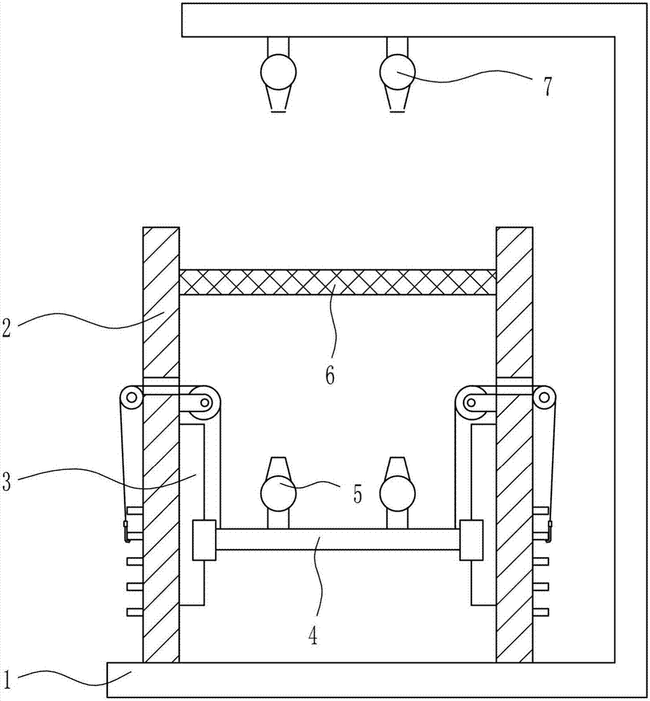
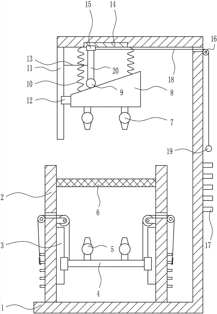
[0028] An air-drying equipment for the production of raw materials for ceiling lamp shades, such as Figure 1-5 As shown, it includes a mounting frame 1, a supporting plate 2, a lower lifting device 3, a lifting plate 4, a first blower 5, a net plate 6 and a second blower 7. The inner bottom of the mounting frame 1 is provided with supporting plates 2 symmetrically. The board 2 is provided with a lower lifting device 3, the lower lifting device 3 is connected with a lifting plate 4, the top of the lifting plate 4 is provided with a first blower 5 symmetrically, and a net plate 6 is connected between the upper part of the inner side of the support plate 2. The plate 6 is located directly above the first blower 5, and the second blower 7 is symmetrically arranged on the left side of the top of the mounting frame 1, and the second blower 7 is located directly above the net plate 6.

Embodiment 2

[0030] An air-drying equipment for the production of raw materials for ceiling lamp shades, such as Figure 1-5 As shown, it includes a mounting frame 1, a supporting plate 2, a lower lifting device 3, a lifting plate 4, a first blower 5, a net plate 6 and a second blower 7. The inner bottom of the mounting frame 1 is provided with supporting plates 2 symmetrically. The board 2 is provided with a lower lifting device 3, the lower lifting device 3 is connected with a lifting plate 4, the top of the lifting plate 4 is provided with a first blower 5 symmetrically, and a net plate 6 is connected between the upper part of the inner side of the support plate 2. The plate 6 is located directly above the first blower 5, and the second blower 7 is symmetrically arranged on the left side of the top of the mounting frame 1, and the second blower 7 is located directly above the net plate 6.

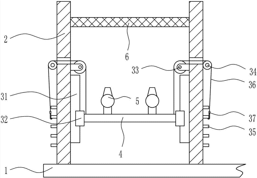
[0031] The lower lifting device 3 includes a first sliding rail 31, a first sliding block 32, a firs...

Embodiment 3

[0033] An air-drying equipment for the production of raw materials for ceiling lamp shades, such as Figure 1-5 As shown, it includes a mounting frame 1, a supporting plate 2, a lower lifting device 3, a lifting plate 4, a first blower 5, a net plate 6 and a second blower 7. The inner bottom of the mounting frame 1 is provided with supporting plates 2 symmetrically. The board 2 is provided with a lower lifting device 3, the lower lifting device 3 is connected with a lifting plate 4, the top of the lifting plate 4 is provided with a first blower 5 symmetrically, and a net plate 6 is connected between the upper part of the inner side of the support plate 2. The plate 6 is located directly above the first blower 5, and the second blower 7 is symmetrically arranged on the left side of the top of the mounting frame 1, and the second blower 7 is located directly above the net plate 6.

[0034] The lower lifting device 3 includes a first sliding rail 31, a first sliding block 32, a firs...


PUM


Abstract

The invention relates to an air-drying device, in particular to an air-drying device after silk screen printing of raw materials for making ceiling lamp shades. The technical problem to be solved by the present invention is to provide an air-drying equipment after silk screen printing of raw materials used for making ceiling lamp shades, which can be quickly air-dried and the air-drying speed can be adjusted. In order to solve the above-mentioned technical problems, the present invention provides such an air-drying equipment after silk screen printing of raw materials for making ceiling lamp shades, which includes a mounting frame, a support plate, a lower lifting device, a lifting plate, a first blower, etc.; the bottom of the mounting frame is symmetrical left and right Support boards are provided, and lower lifting devices are arranged on the supporting boards, and lifting plates are connected between the lower lifting devices, and first blowers are symmetrically arranged on the top of the lifting plates. In the present invention, through the mutual cooperation of the first blower and the second blower, the raw materials on the screen can be quickly air-dried, and the upper and lower lifting devices and the wedge-shaped blocks that can move up and down are added.

Description

Technical field [0001] The invention relates to an air-drying equipment, in particular to an air-drying equipment after silk-printing of raw materials for making ceiling lamp shades. Background technique [0002] Ceiling light is a kind of light fixture. As the name suggests, the top of the light fixture is relatively flat and the bottom is completely attached to the roof when installed, so it is called ceiling light. Light sources include ordinary white bulbs, fluorescent lamps, high-intensity gas discharge lamps, tungsten halogen lamps, LEDs, etc. At present, the most popular ceiling lamp on the market is the LED ceiling lamp, which is often used in various places such as homes, offices, and entertainment venues. When making the ceiling lamp shade, the raw materials need to be dried after the silk screen is completed, which is a long process. [0003] In summary, there is a need to develop a fast-drying and adjustable-drying speed-adjustable air-drying equipment for the product...

Claims


Application Information

Patent Timeline
Patent Type & Authority Applications(China)
IPC IPC(8): F26B9/10F26B21/00F26B25/00
CPCF26B9/10F26B21/00F26B25/00
Inventor 张晓艳
Owner GRACE(NINGBO) LIGHTING CO LTD
Why Eureka
Try Eureka