Direct-type backlight unit and driving method thereof and liquid crystal display device
A technology of a backlight module and a driving method, which is applied in lighting devices, optics, light sources, etc., can solve problems such as affecting image contrast, motion blur, and whitening of dark images, and achieve improved image layering, high dynamic range, and improved image quality. Effects of Static Contrast and Dynamic Contrast
- Summary
- Abstract
- Description
- Claims
- Application Information
AI Technical Summary
Problems solved by technology
Method used
Image
Examples
Embodiment 1
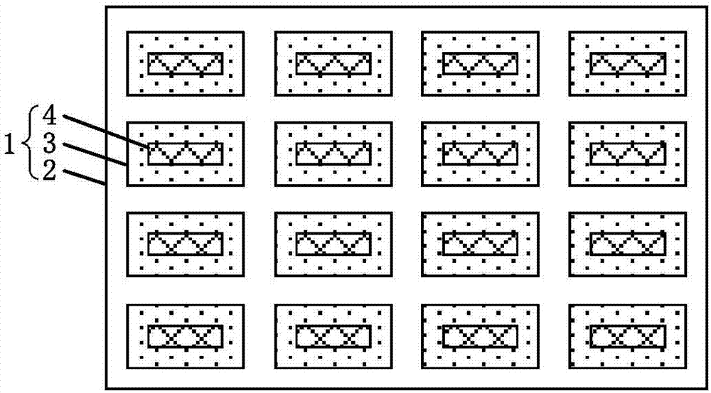
[0044] Such as figure 1 As shown, this embodiment provides a direct type backlight module 1, the direct type backlight module 1 specifically includes a base plate 2, a plurality of drive units 3 disposed on the base plate 2, and a plurality of light emitting elements disposed on the base plate 2 4. Wherein, each driving unit 3 is correspondingly connected to one light emitting element 4 , and the driving unit 3 is used to control the light-emitting duration and light-emitting brightness of the corresponding light-emitting element 4 .
[0045] Specifically, the base plate 2 used in this embodiment may be a transparent base plate made of glass, and a plurality of driving units 3 may be respectively arranged in the base plate 2 . Since each driving unit 3 is correspondingly connected to a light-emitting element 4, each driving unit 3 can independently control the continuous light-emitting time of the light-emitting element 4 connected to it each time it emits light, and independ...
specific Embodiment approach 1
[0056] Such as Figure 5 As shown, a plurality of driving units 3 are arranged in M rows and N columns, wherein M and N are positive integers greater than 1, respectively.
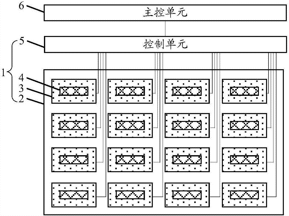
[0057] The control unit 5 may specifically include a row driving module 51 and a column driving module 52 . Wherein, the row driving module 51 includes M output terminals corresponding to the number of rows of the driving unit 3, and the i-th output terminal of the row driving module 51 is connected with the N driving units 3 in the i-th row driving unit 3, i=1 ~M. The row driving module 51 is used to generate and output the first light emission control signal to the driving unit 3 row by row.
[0058] The column driver module 52 includes N output terminals corresponding to the number of columns of the driver unit 3, and the jth output terminal of the column driver module 52 is connected with the jth driver unit 3 in each row driver unit 3, j=1~N . The column driving module 52 is used to generate and...
specific Embodiment approach 2
[0068] Such as Figure 6 As shown, the control unit 5 may specifically include a light-emitting duration driving module 53 and a light-emitting brightness driving module 54 .
[0069] The output terminals of the light-emitting duration driving module 53 are respectively connected to all the driving units 3 . The light-emitting duration driving module 53 is configured to generate and output a second light-emitting control signal to all the driving units 3 , wherein the second light-emitting control signal is a pulse signal. The driving unit 3 is configured to control the light-emitting duration of the corresponding light-emitting element 4 under the action of the second light-emitting control signal.
[0070] The luminous brightness driving module 54 includes multiple output terminals, and the multiple output terminals of the luminous luminance driving module 54 are connected to the multiple driving units 3 in a one-to-one correspondence. The light emitting brightness driving...
PUM
 Abstract
Description
Claims
Application Information
 - R&D
- Intellectual Property
- Life Sciences
- Materials
- Tech Scout
- Unparalleled Data Quality
- Higher Quality Content
- 60% Fewer Hallucinations
Browse by: Latest US Patents, China's latest patents, Technical Efficacy Thesaurus, Application Domain, Technology Topic, Popular Technical Reports.
© 2025 PatSnap. All rights reserved.Legal|Privacy policy|Modern Slavery Act Transparency Statement|Sitemap|About US| Contact US: help@patsnap.com


