Signal transmission device

A signal transmission and signal line technology, applied in the field of signal transmission, can solve problems such as production errors, misjudgment, and inability to transmit the working status of the main contact synchronously, so as to ensure performance and life, and prevent misjudgment.

Active Publication Date: 2017-09-08
NO 13 ELECTRICAL APPLIANCES +1
View PDF5 Cites 0 Cited by
  • Summary
  • Abstract
  • Description
  • Claims
  • Application Information

AI Technical Summary

Problems solved by technology

If the main contacts pass through the overload current for a long time, frequent starting and stopping, etc., overheating or welding will occur
The welding phenomenon will have a great impact on the disconnection process of the main contact. If the main contact has a welding phenomenon, then when the auxiliary contact is disconnected (that is, the signal that the auxiliary contact has disconnected the main contact transmitted), the main contact is actually still in the bonding state, and the auxiliary contact cannot transmit the working state of the main contact synchronously, causing the transmitted signal to be inconsistent with the actual state, resulting in misjudgment, which is likely to cause serious damage production error
[0003] In addition, the transmitting signal end and the receiving signal end of the prior art are in the same space. If the working environment of the signal sending end is harsh (dusty, humid or toxic gas, etc.), the transmitting signal end and the receiving signal end cannot be in the same space. , but it is necessary to know the state in this space in time and accurately, then the structure type of the prior art can no longer be applied

Method used


Image

  • Signal transmission device
  • Signal transmission device
  • Signal transmission device

Examples


Embodiment 1

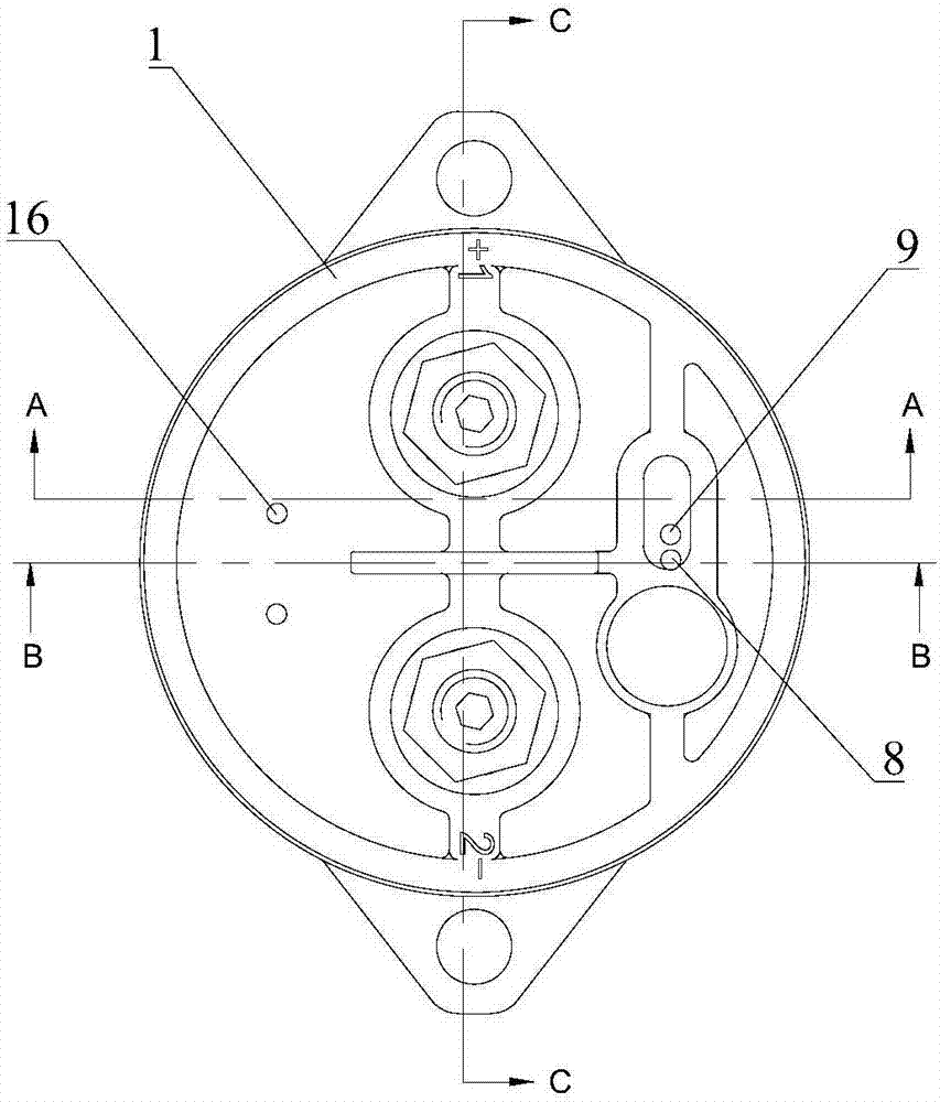
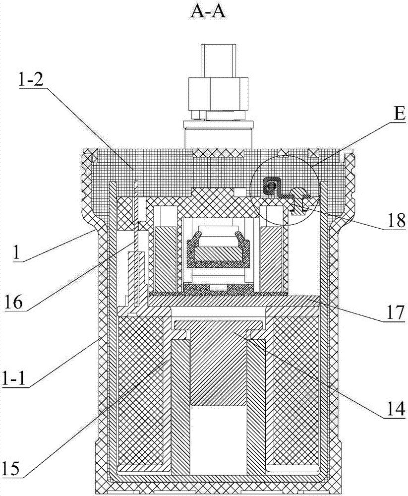
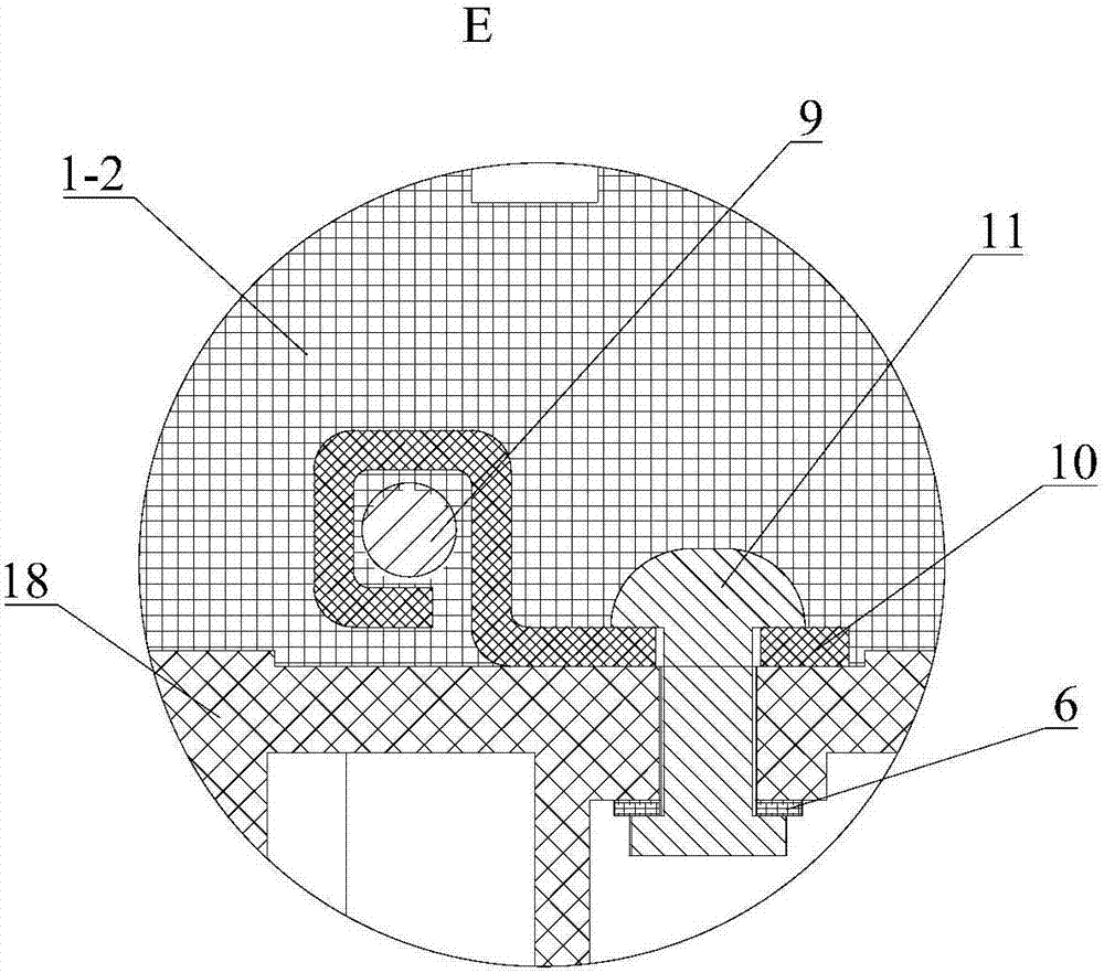
[0043] Please refer to Figure 1 to Figure 7 , Embodiment 1 of the present invention is: a signal transmission device, including an airtight housing 1, a magnet 14, a coil 15, a push rod 2, a touch bridge 3, a support 4, a terminal post 5, an auxiliary contact plate 6, an auxiliary Contact 7, first signal line 8 and second signal line 9, the housing 1 includes a base 1-1 and a cover 1-2, the cover 1-2 is a sealant, the first signal line 8 One end of the first signal line 8 and the second signal line 9 are sealed in the sealant, and the other ends of the first signal line 8 and the second signal line 9 protrude from the cover 1-2. Of course, the cover 1-2 can also be replaced by ceramics. When the cover 1-2 is made of ceramics, Kovar alloy is brazed between the periphery of the cover 1-2 and the base 1-1 to ensure that the housing 1 has better sealing effect.

[0044] The magnet 14 and the coil 15 are arranged in the housing 1, the coil 15 is arranged around the magnet 14, th...


PUM


Abstract

The invention discloses a signal transmission device including an airtight housing, a push rod, a touch bridge, a support piece, a wiring post, an auxiliary contact board, an auxiliary contact and two signal lines. The push rod is arranged in the housing. The contact bridge sleeves the upper part of the push rod. The support rod is in rigid connection with the contact bridge. The wiring post is arranged above the contact bridge. The auxiliary contact point is fixed above the support piece. The auxiliary contact board is arranged between the auxiliary contact point and the support piece and the end of the auxiliary contact board adjacent to the auxiliary contact point is suspended and the other end of the auxiliary contact board is fixed in the housing. One signa line is connected to the auxiliary contact point while the other signal line is connected to the auxiliary contact board. The sum of the distance from the support board to the auxiliary contact board and the distance from the auxiliary contact board to the auxiliary contact point is smaller than the distance from the contact bridge to the wiring post. By adopting the signal transmission device, error judgment caused by main contact fusion welding can be prevented effectively.

Description

technical field [0001] The present invention relates to the technical field of signal transmission, in particular to a signal transmission device. Background technique [0002] At present, the auxiliary contact and the main contact are generally designed synchronously, and the auxiliary contact is usually used to transmit signals to display the on-off status of the main contact. If the main contacts pass the overload current for a long time, frequent starting and stopping, etc., overheating or welding will occur. The welding phenomenon will have a great impact on the disconnection process of the main contact. If the main contact has a welding phenomenon, then when the auxiliary contact is disconnected (that is, the signal that the auxiliary contact has disconnected the main contact transmitted), the main contact is actually still in the bonding state, and the auxiliary contact cannot transmit the working state of the main contact synchronously, causing the transmitted signa...

Claims


Application Information

Patent Timeline
Patent Type & Authority Applications(China)
IPC IPC(8): H01H9/16H01H1/58H01H9/04
CPCH01H1/58H01H9/04H01H9/16
Inventor 刘文明席志刚贺小良陈礼宁汪彤赵振刚苗亚娥
Owner NO 13 ELECTRICAL APPLIANCES
Why Eureka
Try Eureka