Check patentability & draft patents in minutes with Patsnap Eureka AI!

LED undervoltage protection circuit

An under-voltage protection and circuit technology, applied in the protection of under-voltage or no-voltage response, can solve problems such as affecting the stability of the circuit and reducing the filtering effect of the circuit, and achieve the effect of simple circuit, sensitive response, and avoidance of use.

Inactive Publication Date: 2017-09-08
湖州灵感电子科技有限公司
View PDF3 Cites 0 Cited by
  • Summary
  • Abstract
  • Description
  • Claims
  • Application Information

AI Technical Summary

Problems solved by technology

The undervoltage protection circuit of the prior art usually uses more capacitive components, because each charge and discharge of the capacitor will bring a larger load, and at the same time, the capacitor will also generate parasitic inductance, thereby reducing the filtering effect of the circuit and affecting the stability of the circuit

Method used


Image

  • LED undervoltage protection circuit

Examples


Embodiment Construction

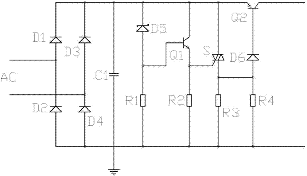
[0016] The embodiments involved in the present invention will be described in further detail below in conjunction with the accompanying drawings.

[0017] Such as figure 1 As shown, an LED undervoltage protection circuit includes resistors R1-R4, voltage regulator diode D5, diode D6, first triode Q1, second triode Q2, and thyristor switch S; the first three The base of the transistor Q1 is respectively connected to the positive terminal of the Zener diode D5 and one end of the resistor R1, and the collector of the first transistor Q1 is respectively connected to the negative terminal of the Zener diode D5 and the emitter of the second transistor Q2. connection, the emitter of the first triode Q1 is respectively connected with the gate of the thyristor switch S and one end of the resistor R2; the base of the second triode Q2 is connected with the negative terminal of the regulator D6, and the second and third The collector of the pole tube Q2 is connected to the load; the posi...


PUM


Abstract

The invention provides an LED undervoltage protection circuit including a resistor R1, a resistor R2, a resistor R3, a resistor R4, a voltage stabilizing diode D5, a voltage stabilizing diode D6, a first triode Q1, a second triode Q2 and a controllable silicon switch S. The base electrode of the first triode Q1 is connected with the positive terminal of the voltage stabilizing diode D5 and one end of the resistor R1. The collector electrode of the first triode Q1 is connected with the negative terminal of the voltage stabilizing diode D5 and the emitting electrode of the second triode Q2. The emitting electrode of the first triode Q3 is connected with the gate electrode of the controllable silicon switch S and one end of the resistor R2. The base electrode of the second triode Q2 is connected with the negative terminal of the voltage stabilizing diode D6. The collector electrode of the second triode Q2 is connected with a load. The positive terminal of the voltage stabilizing diode D6 Is connected with the one end of the resistor r3 and one end of the resistor R4. The other end of the resistor R1, the resistor R2, the resistor R3 and the resistor R4 are connected to the ground. According to the invention, use of capacitance elements is avoided, circuit stability is improved, circuit structure is simplified and circuit reaction flexibility is improved.

Description

[0001] Technical field: [0002] The invention relates to an electronic circuit, in particular to an LED undervoltage protection circuit. [0003] Background technique: [0004] Emergency industrial lights often encounter sudden power outages, etc., and need to be equipped with rechargeable batteries such as Ni-MH, so they have higher requirements for overvoltage and undervoltage protection. The undervoltage protection circuit in the prior art usually uses more capacitive components, because each charge and discharge of the capacitor will bring a larger load, and the capacitor will also generate parasitic inductance, thereby reducing the filtering effect of the circuit and affecting the stability of the circuit. [0005] Invention content: [0006] (1) Solved technical problems [0007] In order to solve the above problems, the present invention provides an LED undervoltage protection circuit, which avoids the use of capacitive components. [0008] (2) Technical solutions ...

Claims


Application Information

Patent Timeline
Patent Type & Authority Applications(China)
IPC IPC(8): H02H3/24
CPCH02H3/24
Inventor 施卫杰
Owner 湖州灵感电子科技有限公司
Features
  • R&D
  • Intellectual Property
  • Life Sciences
  • Materials
  • Tech Scout
  • Unparalleled Data Quality
  • Higher Quality Content
  • 60% Fewer Hallucinations
Learn More