
Flyback type power supply control system

A technology of power control and power controller, which is applied in the direction of control/regulation system, electrical components, and adjustment of electrical variables, etc., can solve the problems of many peripheral circuits, large control chip packaging volume, and large power supply volume, so as to reduce complexity, Reduce system application cost and multi-safety protection effect

Inactive Publication Date: 2017-09-08
成都启臣微电子股份有限公司
View PDF5 Cites 2 Cited by
  • Summary
  • Abstract
  • Description
  • Claims
  • Application Information

AI Technical Summary

Problems solved by technology

In applications that require higher reliability, the power supply system is required to provide the above-mentioned safety protection. However, due to the limitation of the pin number of the control chip, more safety protection cannot be provided, so in order to realize these safety protections, the control chip needs more pins for sampling and detection, and this will inevitably lead to problems such as large package volume of the control chip and many peripheral circuits, which will cause defects such as high system application cost and large power supply

Method used


Image

  • Flyback type power supply control system
  • Flyback type power supply control system
  • Flyback type power supply control system

Examples


Embodiment Construction

[0016] The following will clearly and completely describe the technical solutions in the embodiments of the present invention with reference to the accompanying drawings in the embodiments of the present invention. Obviously, the described embodiments are only some, not all, embodiments of the present invention. Based on the embodiments of the present invention, all other embodiments obtained by persons of ordinary skill in the art without making creative efforts belong to the protection scope of the present invention.

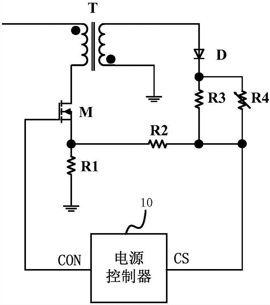
[0017] refer to figure 1 , is a schematic diagram of the principle of the flyback power supply control system according to the first embodiment of the present invention. The flyback power supply control system of this embodiment is mainly applied to an AC-DC power supply system, which includes a transformer T, a power tube M, a diode D, a first resistor R1, a second resistor R2, a third resistor R3 and a power controller 10 . One end of the primary winding o...


PUM


Abstract

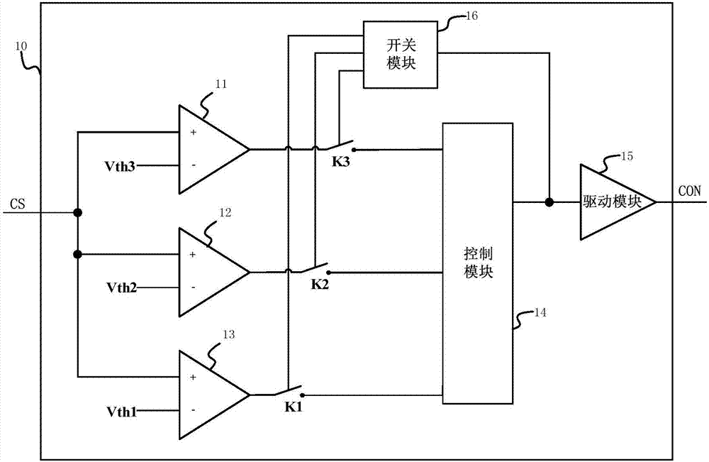
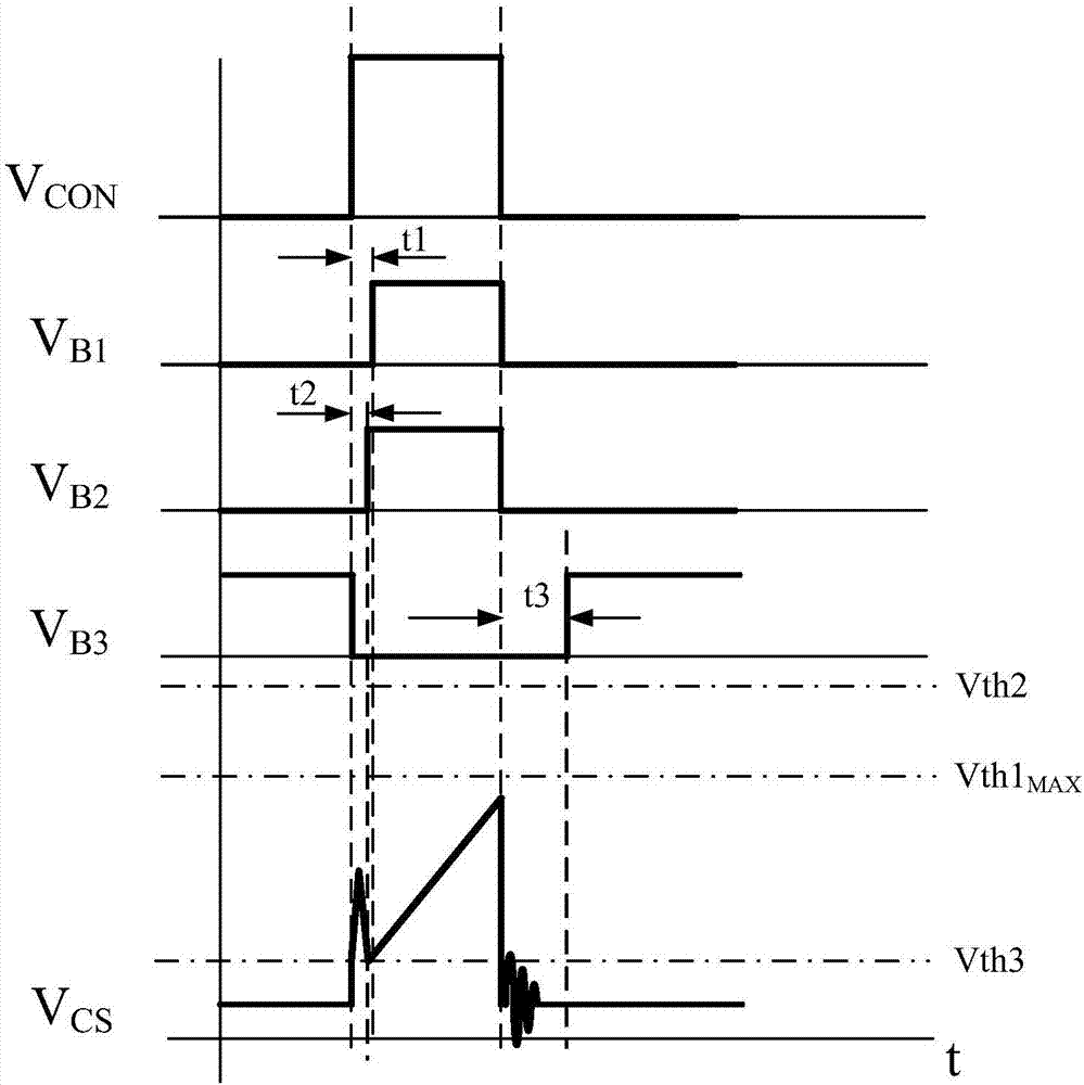
The invention discloses a flyback type power supply control system. The flyback type power supply control system comprises a transformer, a power tube, a diode, a first resistor, a second resistor, a third resistor and a power supply controller, wherein one end of a primary winding of the transformer is connected with an input system voltage, the other end of the primary winding is connected with a drain end of the power tube, a source end of the power tube is connected with the ground through the first resistor, one end of an auxiliary winding of the transformer is connected with the ground, the other end of the auxiliary winding sequentially passes through the diode, the third resistor and the second resistor and is connected with the source end of the power tube, the power supply controller is provided with a sampling end and a control end, the sampling end is connected between the third resistor and the second resistor, the control end is connected with a gate end of the power tube, and the power supply controller is used for driving the power tube to be periodically switched on, acquiring a detection voltage during switch-on and switch-off periods of the power tube, judging whether the working condition is an abnormal sate or not according to the detection voltage and driving the power tube to be switched off when the working condition is judged to be an abnormal state. By the mode, more safety protection can be achieved by using a few pins.

Description

technical field [0001] The invention relates to the technical field of basic electronic circuits, in particular to a flyback power supply control system. Background technique [0002] The flyback power supply system is more and more widely used in the existing power supply system, so its safety and reliability are also paid more attention by users. The safety standards of various countries also require the safety and security of power supply products and household appliances. Various tests and specifications are performed for reliability. [0003] In the application of the current flyback power supply system, the small size has become an important factor to attract more manufacturers to use. In the existing flyback topology applications, especially in secondary side flyback applications, output overvoltage protection, external overtemperature protection, etc. are required, and in some power systems, the leading edge of the peak current of the primary winding of the transfor...

Claims


Application Information

Patent Timeline
Patent Type & Authority Applications(China)
IPC IPC(8): H02M3/335H02M1/08H02H7/10
CPCH02H7/10H02M1/08H02M3/33523
Inventor 许刚颍唐波向磊马强吴强
Owner 成都启臣微电子股份有限公司
Learn More