
A constant speed drive shaft moving joint assembly machine

A constant-velocity drive shaft and assembly machine technology, applied in metal processing equipment, metal processing, manufacturing tools, etc., can solve problems such as inability to adapt to automated production line operations, poor product consistency and safety, and low production efficiency, so as to ensure product quality Consistency and safety, increased automation, and increased productivity

Active Publication Date: 2019-04-19
SIASUN ROBOT & AUTOMATION LIMITED BY SHARE
View PDF6 Cites 0 Cited by
  • Summary
  • Abstract
  • Description
  • Claims
  • Application Information

AI Technical Summary

Problems solved by technology

[0002] At present, in the automobile production process, the assembly of the moving joint of the constant velocity drive shaft is mainly completed manually through a special press and simple tooling. This assembly operation method has low production efficiency, high cost, poor product consistency and safety, and even worse. Unable to adapt to automated production line operations, it is extremely necessary to carry out automation improvements to meet current production needs

Method used


Image

  • A constant speed drive shaft moving joint assembly machine
  • A constant speed drive shaft moving joint assembly machine
  • A constant speed drive shaft moving joint assembly machine

Examples


Embodiment 1

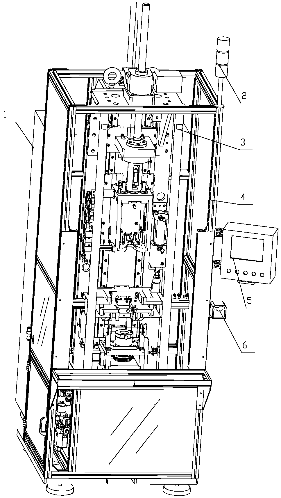
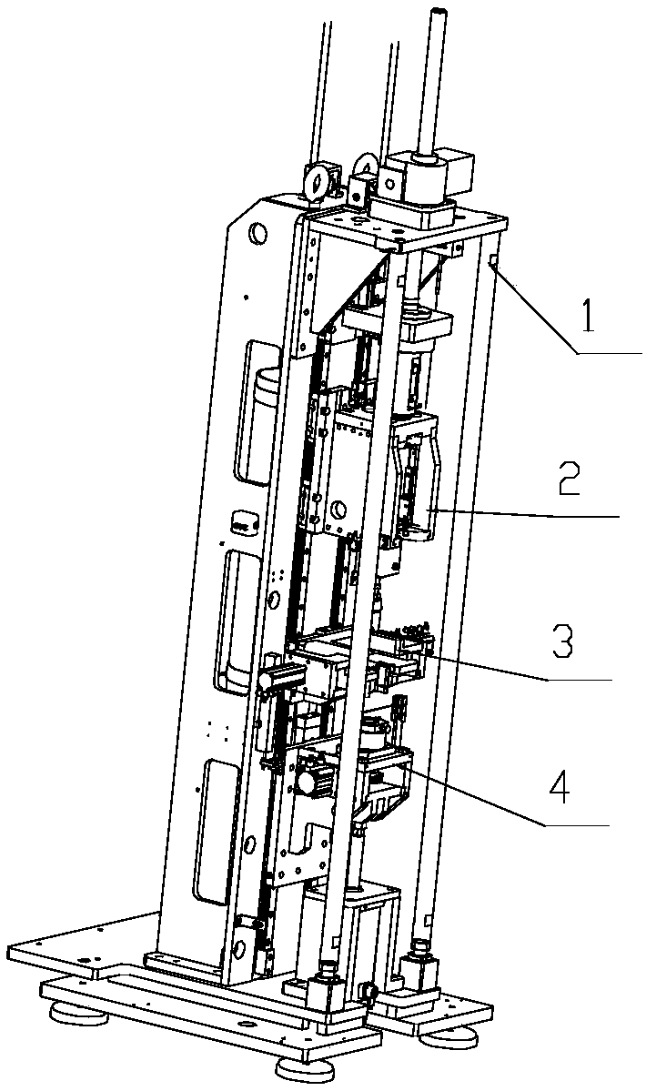
[0045] Such as figure 1 , figure 2 , Figure 4 to Figure 16 As shown, a constant speed drive shaft moving section assembly machine includes an electrical cabinet 1, a three-color warning light 2, a button control cabinet 5, a manual button panel 6, a host and a moving section assembly tool, the host includes a rack assembly, and the upper The moving mechanism, the middle moving mechanism and the lower moving mechanism, the upper moving mechanism, the middle moving mechanism and the lower moving mechanism are all slidably connected to the frame assembly, and the upper moving mechanism, the middle moving mechanism and the lower moving mechanism are connected to a PLC control system , the main working devices of the PLC control system are installed in the electrical cabinet 1, and the assembly tooling of the moving section is connected with the upper moving mechanism and the lower moving mechanism. The electrical cabinet 1 is arranged on the back of the main engine, and the th...

Embodiment 2

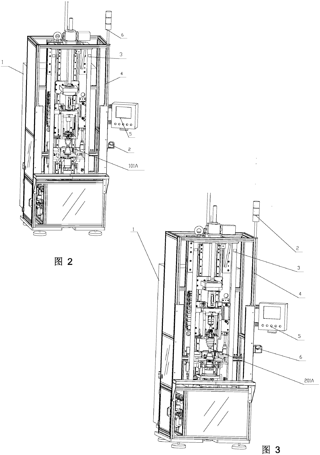
[0048] Such as image 3 , Figure 17a to Figure 22 The moving joint assembly tool is a three-pin joint assembly tool, which is composed of upper and lower two-section modules. The three-pin joint assembly tool includes an upper tool outer cylinder 204, and the upper tool outer cylinder 204 is provided with a light blocking sheet 201, Block 211, revolving pin 206, revolving pin 206 is provided with swing claw 207, swing claw 207 is provided with O-ring 208, outer cylinder 204 is also provided with flange 202, flange 202 is provided with first guide pin 203, the outer cylinder 204 is also provided with an inner cylinder 205, the inner cylinder 205 is provided with an upper top 210, the upper top 210 is provided with a second guide pin 209, and the lower top fixing seat 212 of the lower tooling is provided with a compression spring 213, the stage clip 213 is provided with the lower top 214, and the top holder 212 is also provided with a flange 215 and a guide spline sleeve 216. ...


PUM


Abstract

The invention discloses an equal-speed drive shaft movable joint assembling machine. The equal-speed drive shaft movable joint assembling machine comprises a host and a movable joint assembling tool. The host comprises a rack assembly, an upper moving mechanism, a middle moving mechanism and a lower moving mechanism. The upper moving mechanism, the middle moving mechanism and the lower moving mechanism are connected to the rack assembly in a sliding manner and are connected into a PLC control system. The movable joint assembly tool is connected with the upper moving mechanism and the lower moving mechanism. According to the equal-speed drive shaft movable joint assembling machine, the automatic assembling level of equal-speed drive shaft movable joints can be improved, the operation manner is optimized, and manual work is reduced; and the labor intensity and the production cost are reduced, the production efficiency is improved, and product consistency and safety are guaranteed.

Description

technical field [0001] The invention relates to an automatic assembly equipment for automobile parts, more specifically, it relates to an assembly machine for moving joints of constant-velocity drive shafts. Background technique [0002] At present, in the automobile production process, the assembly of the moving joint of the constant velocity drive shaft is mainly completed manually through a special press and simple tooling. This assembly operation method has low production efficiency, high cost, poor product consistency and safety, and even worse. Unable to adapt to automated production line operations, it is extremely necessary to improve automation to meet current production needs. Contents of the invention [0003] The existing assembly operation method of the moving joint of the constant velocity drive shaft of the automobile has low production efficiency, high cost, and poor product consistency and safety. In order to overcome these defects, the present invention p...

Claims


Application Information

Patent Timeline
Patent Type & Authority Patents(China)
IPC IPC(8): B23P19/02B23P19/00
CPCB23P19/006B23P19/021
Inventor 李正刚陈锋张启辉潘鑫张晓帅李明杰乐胜豪
Owner SIASUN ROBOT & AUTOMATION LIMITED BY SHARE
Features
  • Generate Ideas
  • Intellectual Property
  • Life Sciences
  • Materials
  • Tech Scout
  • Unparalleled Data Quality
  • Higher Quality Content
  • 60% Fewer Hallucinations
Learn More