
Turbine disk, engine and aircraft

A turbine disk and engine technology, applied to engine components, machines/engines, mechanical equipment, etc., can solve the problems of turbine disk 1 structural deformation, affecting component accuracy, long processing cycle, etc., and achieve the effect of reducing weight

Active Publication Date: 2017-09-12
AECC HUNAN AVIATION POWERPLANT RES INST
View PDF5 Cites 0 Cited by
  • Summary
  • Abstract
  • Description
  • Claims
  • Application Information

AI Technical Summary

Problems solved by technology

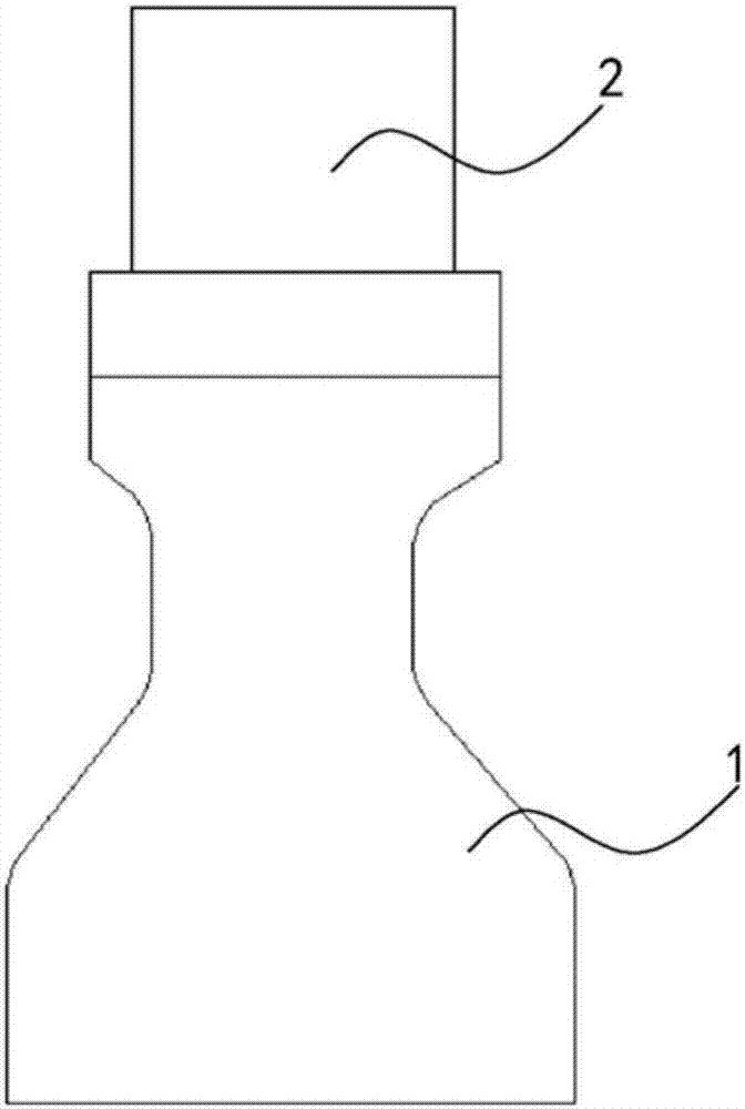
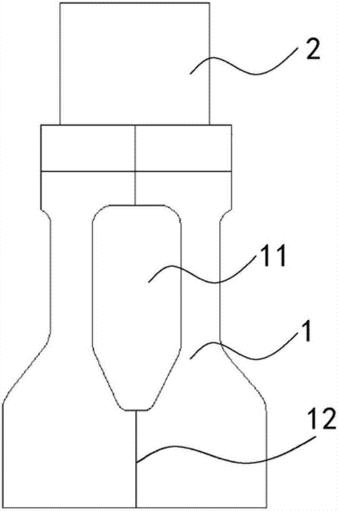
[0004] However, the cavity 11 in the turbine disk 1 needs to be connected by welding, for example, the welding seam 12 is arranged at a symmetrical position, which easily leads to large structural deformation during the welding process, affects the precision of the parts, and has complicated processes and costs. High and long processing cycle
In addition, after being connected by welding, the cavity 11 is closed to accommodate air, and the structure of the turbine disk 1 is easily deformed due to thermal expansion and contraction during use.

Method used


Image

  • Turbine disk, engine and aircraft
  • Turbine disk, engine and aircraft
  • Turbine disk, engine and aircraft

Examples


Embodiment Construction

[0036] Example embodiments will now be described more fully with reference to the accompanying drawings. Example embodiments may, however, be embodied in many forms and should not be construed as limited to the embodiments set forth herein; rather, these embodiments are provided so that this disclosure will be thorough and complete, and will fully convey the concept of example embodiments to those skilled in the art. The same reference numerals in the drawings denote the same or similar structures, and thus their detailed descriptions will be omitted.

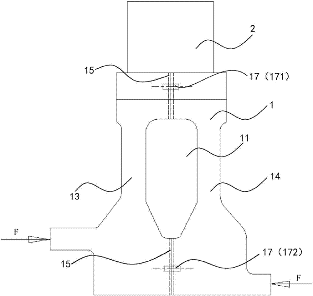
[0037] combine Figure 3 to Figure 7 As shown, a turbine disk 1 according to a preferred embodiment of the present invention is generally integrally formed as a disk-like structure for rotation around its central axis. The turbine disk 1 of the present invention includes a left disk 13 and a right disk 14 opposite to each other, and grooves are respectively formed on opposite sides of the two to form an annular cavity 11 that...


PUM


Abstract

The invention relates to the field of engines and discloses a turbine disk, an engine and an aircraft. The turbine disk comprises a left disk and a right disk which are arranged opposite to each other; groove parts are respectively formed in the opposite sides of the left disk and the right disk so as to be buckled with each other to form a cavity; and the cavity communicates to an external environment by a vent hole extending in a through way. The cavity is formed in the turbine disk disclosed by the invention, so that the weight can be reduced, and the development demand of light weight is met. In addition, due to the formation of the vent hole for communicating the cavity with the external environment, air is allowed to freely enter the cavity or to be exhausted from the cavity, so that structural distortion caused by thermal expansion and cold contraction of the turbine disk can be avoided.

Description

technical field [0001] The invention relates to the field of engines, in particular to a turbine disc. On this basis, the present invention also relates to an engine with the turbine disk and an aircraft with the engine. Background technique [0002] As competition in the aviation industry continues to intensify, turbine disks used in aeroengines (or other gas turbine engines) are increasingly lightweight. However, in order to have higher safety and reliability, the structural design of the turbine disk is also subject to relatively large limitations. [0003] figure 1 Shown is a schematic diagram of the connection structure between the turbine disk 1 and the blade 2 in the conventional technology. Among them, the turbine disk 1 is a solid structure with high weight, which is not suitable for lightweight development requirements. In this regard, proposed figure 2 The shown turbine disk 1 has a cavity 11 and is connected with blades 2, and by properly setting the positi...

Claims


Application Information

Patent Timeline
Patent Type & Authority Applications(China)
IPC IPC(8): F01D5/02F01D5/06
CPCF01D5/02F01D5/066
Inventor 蔡显新唐俊鹏齐思鑫
Owner AECC HUNAN AVIATION POWERPLANT RES INST
Learn More