Hub clamping device
A technology of clamping device and wheel hub, applied in the direction of the chuck, etc., can solve the problems of high cost, complex structure, poor reliability, etc., and achieve the effect of low cost, good reliability, and large loading and unloading space
- Summary
- Abstract
- Description
- Claims
- Application Information
AI Technical Summary
Problems solved by technology
Method used
Image
Examples
Embodiment Construction
[0012] The present invention will be further described in detail below in conjunction with the accompanying drawings and examples. The following examples are explanations of the present invention and the present invention is not limited to the following examples.
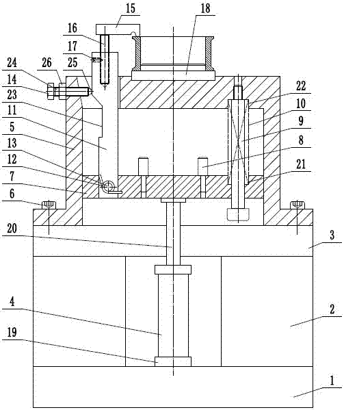
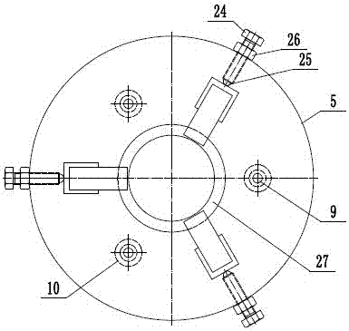
[0013] Such as figure 1 and figure 2 As shown, a hub clamping device includes a lower base 1, a frame 2, an upper support 3, a drive cylinder 4, a support seat 5, a mounting bolt 6, a supporting plate 7, a limit pin 8, a guide rod 9, Compression spring 10, pull rod 11, torsion spring 12, pull rod pin 13, guide assembly 14, claw 15, claw connecting rod 16, fastening screw 17, hub centering support seat 18, the frame 2 is fixed on the lower base 1, the upper support 3 is fixed on the frame 2, the support seat 5 is installed on the upper support 3 through the mounting bolt 6, the number of the guide rods 9 is three, and they are evenly distributed, so The upper end of the guide rod 9 is threadedly connected to the s...
PUM
 Abstract
Description
Claims
Application Information
 - R&D
- Intellectual Property
- Life Sciences
- Materials
- Tech Scout
- Unparalleled Data Quality
- Higher Quality Content
- 60% Fewer Hallucinations
Browse by: Latest US Patents, China's latest patents, Technical Efficacy Thesaurus, Application Domain, Technology Topic, Popular Technical Reports.
© 2025 PatSnap. All rights reserved.Legal|Privacy policy|Modern Slavery Act Transparency Statement|Sitemap|About US| Contact US: help@patsnap.com


