Negative pressure equal liquid level height control liquid filling device

A negative pressure filling and filling device technology, applied in liquid bottling, liquid filling, liquid processing and other directions, can solve the problems affecting the purchase rate, difficulty, and inability to achieve liquid level filling of different bottles, etc. Eliminate the problem of environmental pollution and eliminate the effect of cost increase

Inactive Publication Date: 2017-09-15
徐志明 +1
View PDF0 Cites 7 Cited by
  • Summary
  • Abstract
  • Description
  • Claims
  • Application Information

AI Technical Summary

Problems solved by technology

[0002] With the improvement of people's living standards, the demand for bottled condiments and canned fruits continues to increase. In the production process of these products, how to realize the contour of the liquid level in the bottle is an important reason that affects the sales of products. People are shopping At the same time, if the liquid level of the same bottled product is different, people usually choose the one with high liquid level, and people generally don’t choose the one with low liquid level. The quality cannot be guaranteed, which directly affects people's purchase rate
Due to bottle packaging products, especially canned fruit products, it is very difficult to fill the liquid level to the same height, because the volume of the inner cavity of the bottle is poor, and there are errors in the size and height of the bottle. When filling the liquid, there are lumps of pulp with different volumes in the bottle, and the current liquid filling usually adopts the constant volume method or the flow method, and these conventional liquid filling methods cannot achieve equal liquid levels in different bottles. filling

Method used


Image

  • Negative pressure equal liquid level height control liquid filling device
  • Negative pressure equal liquid level height control liquid filling device
  • Negative pressure equal liquid level height control liquid filling device

Examples


Embodiment 1

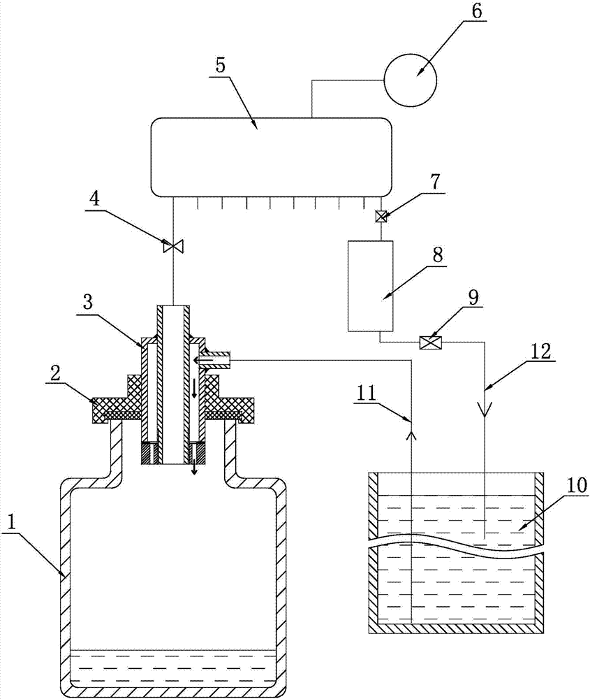
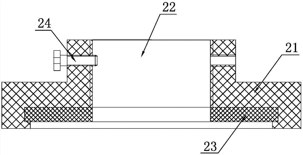
[0028] A liquid level control liquid filling device such as negative pressure, such as Figure 1-7 As shown, it includes bottle body 1, bottle mouth sealing gland 2, negative pressure filling head 3, suction valve 4, negative pressure chamber 5, vacuum pump 6, upper liquid discharge valve 7, transitional liquid storage tank 8, lower liquid discharge The valve 9 and the material liquid box 10, the bottle mouth sealing gland 2 includes a gland body 21, a connecting inner hole 22, a bottle mouth sealing gasket 23 and an adjusting screw 24, and the connecting inner hole 22 is arranged at the center of the gland body 21 , used to install the negative pressure filling head 3, the bottle mouth gasket 23 is arranged on the lower end surface of the gland body 21, and the adjusting screw 24 is screwed on the shoulder of the gland body 21 to limit the negative pressure filling head 3 extend the length of the bottle mouth sealing gasket 23, the negative pressure filling head 3 includes an...

Embodiment 2

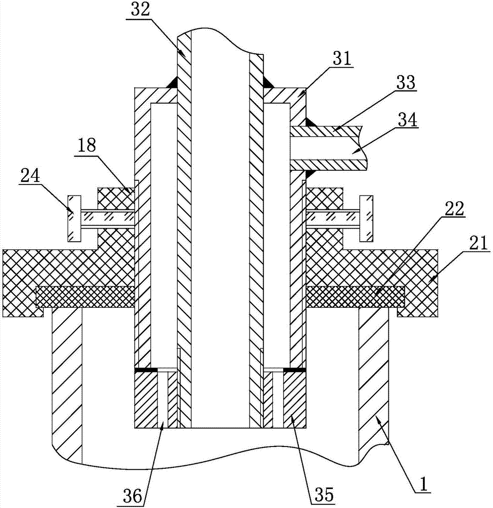
[0030] On the basis of Example 1, the negative pressure filling head 3 is optimized, that is, a liquid level control end cap 35 is arranged at the lower end of the negative pressure filling head 3, and a central threaded hole is arranged at the center of the liquid level control end cap 35 , the outer circle of the lower section of the inner casing 32 is provided with an external thread, and the liquid level control end cap 35 is screwed on the external thread of the inner casing 32 through the central threaded hole, and the upper end surface of the liquid level control end cap 35 is connected to the outer casing The lower end surface of 31 is sealed and butted, and a liquid injection hole 36 is arranged on the lower end surface of the liquid level control end cover 35, and the liquid injection hole 36 communicates with the liquid inlet channel.

Embodiment 3

[0031]Embodiment 3: On the basis of embodiment 1, the negative pressure filling head 3 is optimized, namely the liquid level control end cap 35 is set at the lower end of the negative pressure filling head 3, and the upper end of the liquid level control end cap 35 is set There is an inner concave ring and a smooth center hole, and the side wall of the inner concave ring is provided with a side internal thread, and the outer circle of the lower section of the outer casing 31 is provided with an external thread, and the liquid level control end cap 35 is screwed on the side through the side internal thread hole. On the external thread of the outer sleeve 31.

[0032] In order to facilitate the installation and adjustment between the bottle mouth sealing gland 2 and the negative pressure filling head 3, the connecting inner hole 22 of the bottle mouth sealing gland 2 is designed as a threaded hole, and the outer circle of the negative pressure filling head 3 is provided There ar...


PUM


Abstract

A liquid level control liquid filling device under negative pressure, including a bottle body, a bottle mouth sealing gland, a negative pressure filling head, a suction valve, a negative pressure chamber, a vacuum pump, an upper liquid discharge valve, a transitional liquid storage tank, The lower discharge valve and the material liquid tank, the negative pressure filling head is tightly fitted on the bottle mouth sealing gland, the lower end surface of the bottle mouth sealing gland is sealed and pressed with the bottle mouth, and the lower end surface of the negative pressure filling head extends In the bottle, the negative pressure channel of the negative pressure filling head communicates with the inner cavity of the negative pressure chamber, the liquid inlet channel of the negative pressure filling head communicates with the material liquid tank, and the negative pressure chamber passes through the upper discharge valve and the transitional liquid storage in turn. The tank and the lower drain valve communicate with the feed tank. It adopts the principle of negative pressure liquid suction, which can not only inject liquid into the bottle, but also suck the excess liquid back into the material liquid tank, and can realize equal height liquid level filling of various bottles, solving the problem of At present, ordinary liquid filling machines cannot fill the bottle body at equal heights. It meets the filling requirements of equal liquid level for special commodities such as canned fruit.

Description

technical field [0001] The invention relates to the field of liquid filling, in particular to a liquid filling device capable of achieving equal liquid levels for bottles. Background technique [0002] With the improvement of people's living standards, the demand for bottled condiments and canned fruits continues to increase. In the production process of these products, how to realize the contour of the liquid level in the bottle is an important reason that affects the sales of products. People are shopping At the same time, if the liquid level of the same bottled product is different, people usually choose the one with high liquid level, and people generally don’t choose the one with low liquid level. The quality cannot be guaranteed, which directly affects people's purchase rate. Due to bottle packaging products, especially canned fruit products, it is very difficult to fill the liquid level to the same height, because the volume of the inner cavity of the bottle is poor,...

Claims


Application Information

Patent Timeline
Patent Type & Authority Applications(China)
IPC IPC(8): B67C3/16B67C3/26
CPCB67C3/16B67C3/2634
Inventor 徐志明高志兴
Owner 徐志明
Why Eureka
Try Eureka