
Sulfur and dust removal device

A technology of desulfurization dust collector and cyclone dust collector, which is applied in the direction of chemical instruments and methods, separation of dispersed particles, combined devices, etc., which can solve the problems of large loss, short service life, and low dust removal efficiency

Active Publication Date: 2015-08-26
KEDA INDUSTRIAL GROUP CO LTD
View PDF5 Cites 6 Cited by
  • Summary
  • Abstract
  • Description
  • Claims
  • Application Information

AI Technical Summary

Problems solved by technology

[0002] Today, powder preparation in the ceramic industry basically uses spray drying tower technology, but because this technology needs to burn fossil fuels, the flue gas will contain a large amount of dust and air pollutants such as oxygen sulfide, and desulfurization and dust removal treatment is required before discharge, so it is necessary Supporting use of desulfurization and dust removal equipment
[0003] Existing desulfurization and dust removal equipment mainly include cyclone dust collector, bag filter, wet spray dust removal desulfurizer, electrostatic precipitator; the disadvantage of cyclone dust collector is low dust removal efficiency, and the disadvantage of bag filter is large loss and short service life. The disadvantage of wet spray dust collector and desulfurizer is that white smoke will overflow after spraying, and the disadvantage of electrostatic precipitator is that it consumes a lot of energy

Method used


Image

  • Sulfur and dust removal device
  • Sulfur and dust removal device

Examples


Embodiment Construction

[0026] The following will clearly and completely describe the technical solutions in the embodiments of the present invention with reference to the accompanying drawings in the embodiments of the present invention. Obviously, the described embodiments are only some, not all, embodiments of the present invention. Based on the embodiments of the present invention, all other embodiments obtained by persons of ordinary skill in the art without creative efforts fall within the protection scope of the present invention.

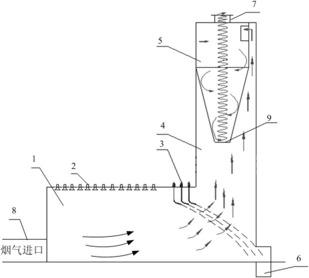
[0027] figure 1 It is a structural schematic diagram of an embodiment of the desulfurization dust remover of the present invention. Such as figure 1 Shown, the desulfurization dust remover of the present embodiment comprises:

[0028] Horizontal spray room 1, desulfurization nozzle 2, cooling nozzle 3, vertical chimney 4, cyclone dust collector 5 and first sewage tank 6;

[0029] Wherein, the vertical chimney 4 is arranged above the side of the horizontal spray ...


PUM


Abstract

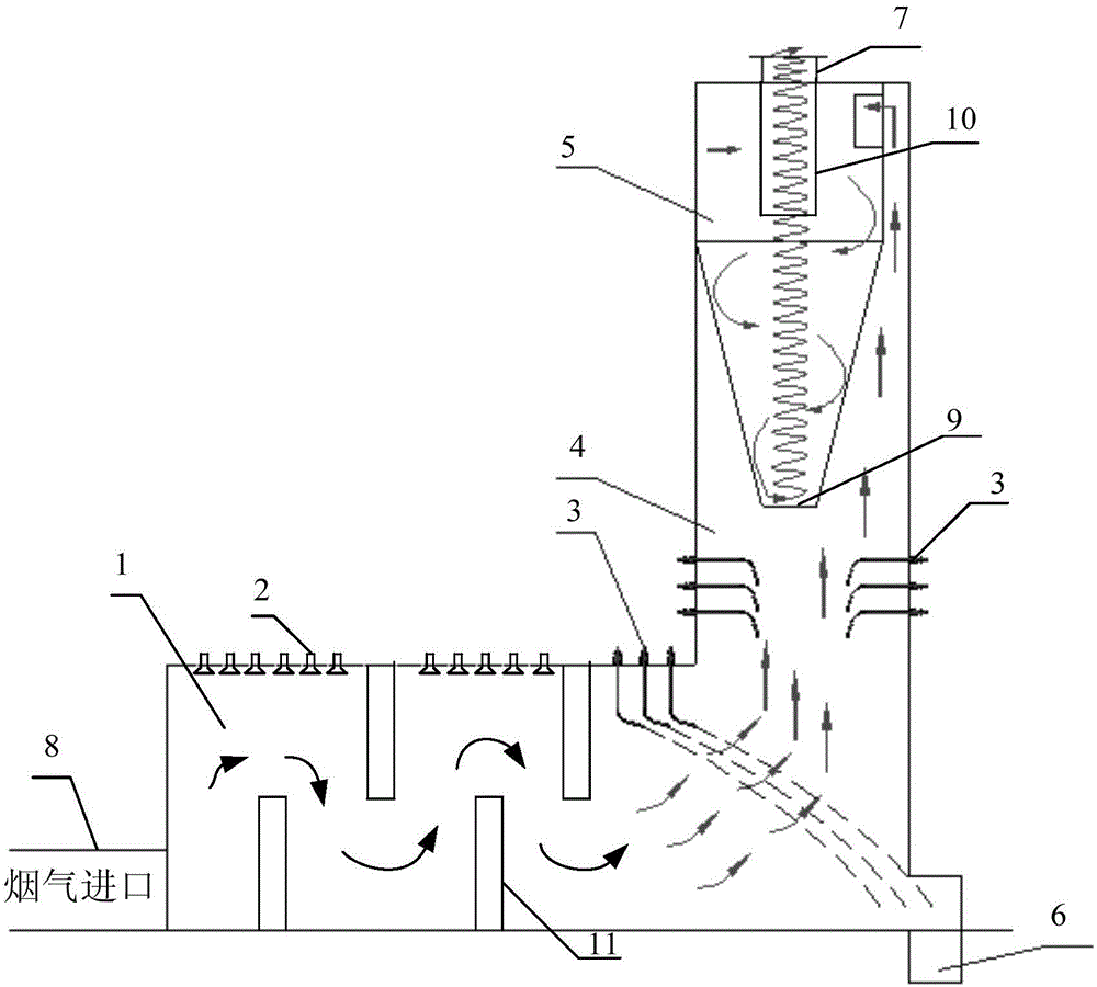
The invention provides a sulfur and dust removal device. The sulfur and dust removal device comprises a horizontal spray room, a sulfur removal spray head, a cooling spray head, a vertical chimney, a cyclone dust remover and a first sewage tank, wherein the vertical chimney is arranged above one side, far away from a flue gas inlet, of the horizontal spray room; the sulfur removal spray head is arranged at the top of one side, close to the flue gas inlet, of the horizontal spray room; the cooling spray head is arranged at the top of one side, close to the vertical chimney, of the horizontal spray room; the first sewage tank is arranged at the bottom of one side, far away from the flue gas inlet, of the horizontal spray room; the cyclone dust remover is arranged in the vertical chimney; a housing of the cyclone dust remover comprises a straight barrel section and a cone section; a gas outlet is formed in the top of the housing of the cyclone dust remover; the flue gas inlet is formed in the side surface at the upper part of the straight barrel section of the housing of the cyclone dust remover; a sewage outlet is formed in the lower end of the cone section of the housing of the cyclone dust remover; a second sewage tank is arranged below the sewage outlet. The sulfur and dust removal device is relatively good in sulfur and dust removal effects.

Description

technical field [0001] The invention relates to the technical field of desulfurization and dust removal, in particular to a desulfurization and dust removal device. Background technique [0002] Today, powder preparation in the ceramic industry basically uses spray drying tower technology, but because this technology needs to burn fossil fuels, the flue gas will contain a large amount of dust and air pollutants such as oxygen sulfide, and desulfurization and dust removal treatment is required before discharge, so it is necessary Supporting use of desulfurization and dust removal equipment. [0003] Existing desulfurization and dust removal equipment mainly include cyclone dust collector, bag filter, wet spray dust removal desulfurizer, electrostatic precipitator; the disadvantage of cyclone dust collector is low dust removal efficiency, and the disadvantage of bag filter is large loss and short service life. The disadvantage of the wet spray dust collector and desulfurizer ...

Claims


Application Information

Patent Timeline
IPC IPC(8): B01D50/00B01D53/78B01D53/50
Inventor 陈水福黄慧林齐人斌
Owner KEDA INDUSTRIAL GROUP CO LTD
Learn More